Table of Contents
The Value of Terminal Block Wiring Diagrams
When it comes to electrical systems, precision and organization are paramount. This is where terminal block wiring diagrams come into play, serving as a visual representation of how various components are connected within a circuit. These diagrams provide a clear roadmap for electricians, technicians, and DIY enthusiasts to follow, ensuring proper installation and maintenance of electrical connections. Understanding terminal block wiring diagrams is not only essential for safety and efficiency but also for troubleshooting issues that may arise in electrical systems.
Components of a Terminal Block Wiring Diagram
1. Terminal Blocks
Terminal blocks are modular, insulated blocks that secure two or more wires together. They provide a convenient way to connect and disconnect wires without the need for soldering or crimping. In a wiring diagram, terminal blocks are represented by symbols that indicate how wires are to be connected.
2. Wires and Connections
Wires play a crucial role in electrical circuits, carrying current from one component to another. In a wiring diagram, different types of wires are color-coded and labeled to denote their function and connection points. Understanding how wires are interconnected is essential for proper circuit design and maintenance.
Interpreting a Terminal Block Wiring Diagram
1. Follow the Flow
When analyzing a terminal block wiring diagram, start by identifying the power source and the direction in which current flows through the circuit. Follow the path of wires and connections to understand how components are linked together within the system.
2. Check for Errors
Inspect the wiring diagram for any discrepancies or misconnections. Errors in wiring can lead to electrical malfunctions or even pose safety hazards. By carefully reviewing the diagram, you can ensure that all connections are made correctly and troubleshoot any issues that may arise.
Tips for Creating a Terminal Block Wiring Diagram
- Use standardized symbols for terminal blocks, wires, and components to maintain clarity and consistency.
- Include a legend or key to explain the meaning of each symbol used in the diagram.
- Label all wires and connections with descriptive text to avoid confusion during installation or maintenance.
Conclusion
In conclusion, terminal block wiring diagrams serve as invaluable tools for understanding and working with electrical systems. By mastering the art of interpreting these diagrams, individuals can navigate complex circuits with confidence and precision. Whether you’re a seasoned electrician or a novice enthusiast, delving into the world of terminal block wiring diagrams can enhance your knowledge and skills in the realm of electrical engineering.
Related to Terminal Block Wiring Diagram
- Telecaster Wiring Diagram 3 Way Switch
- Telecaster Wiring Diagrams
- Telephone Connection Wiring Diagram
- Telephone Line Wiring Diagram
- Telephone Wiring Diagram
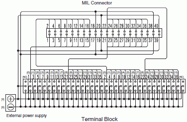
XW2R PLCs Connector Terminal Block Conversion Units For PLCs Dimensions OMRON Industrial Automation
The image title is XW2R PLCs Connector Terminal Block Conversion Units For PLCs Dimensions OMRON Industrial Automation, features dimensions of width 383 px and height 247 px, with a file size of 383 x 247 px. This image image/gif type visual are source from www.ia.omron.com.
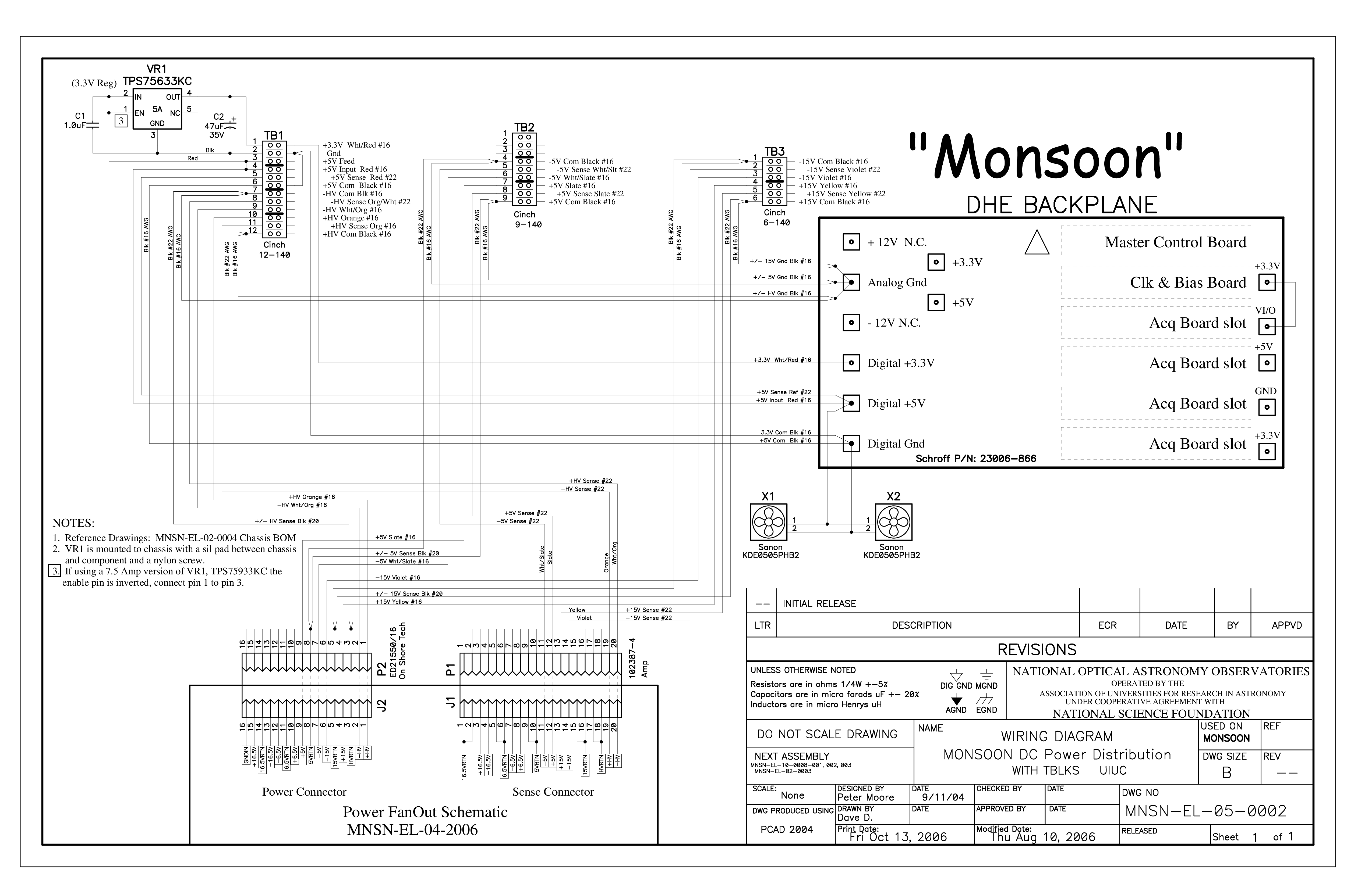
Chassis Wiring Diagram With Terminal Blocks NOIRLab Science
The image title is Chassis Wiring Diagram With Terminal Blocks NOIRLab Science, features dimensions of width 5100 px and height 3300 px, with a file size of 5100 x 3300 px. This image image/png type visual are source from noirlab.edu.
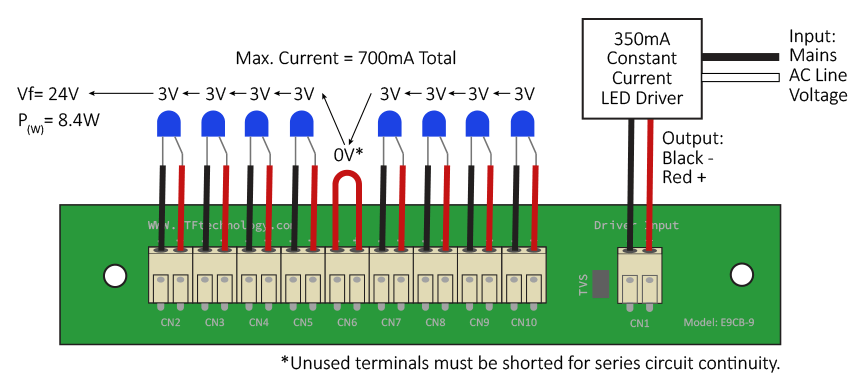
Quick Connect Terminal Blocks LTF Technology
The image title is Quick Connect Terminal Blocks LTF Technology, features dimensions of width 865 px and height 391 px, with a file size of 865 x 391. This image image/png type visual are source from ltftechnology.com.
XW2R PLCs Connector Terminal Block Conversion Units For PLCs Dimensions OMRON Industrial Automation
The image title is XW2R PLCs Connector Terminal Block Conversion Units For PLCs Dimensions OMRON Industrial Automation, features dimensions of width 376 px and height 246 px, with a file size of 376 x 246. This image image/gif type visual are source from www.ia.omron.com.
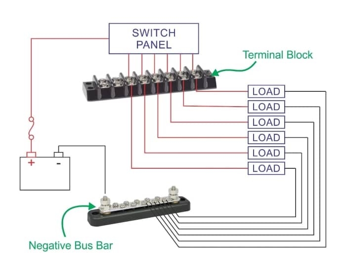
Terminal Block Diagram New Wire Marine
The image title is Terminal Block Diagram New Wire Marine, features dimensions of width 700 px and height 557 px, with a file size of 700 x 557. This image image/jpeg type visual are source from newwiremarine.com
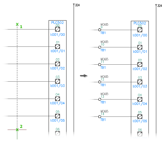
How Are Terminal Blocks Depicted In A Wiring Diagram Electrical Engineering Stack Exchange
The image title is How Are Terminal Blocks Depicted In A Wiring Diagram Electrical Engineering Stack Exchange, features dimensions of width 550 px and height 480 px, with a file size of 550 x 480. This image image/png type visual are source from electronics.stackexchange.com.
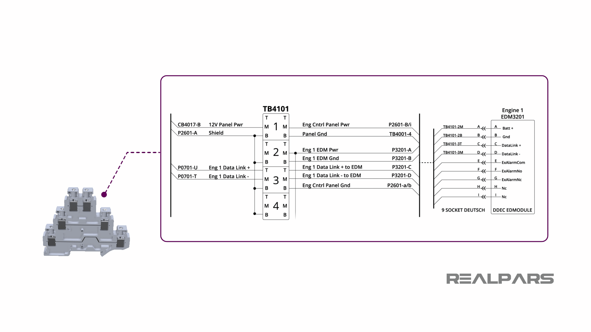
Terminal Blocks Explained RealPars
The image title is Terminal Blocks Explained RealPars, features dimensions of width 1920 px and height 1080 px, with a file size of 1920 x 1080. This image image/png type visual are source from www.realpars.com.
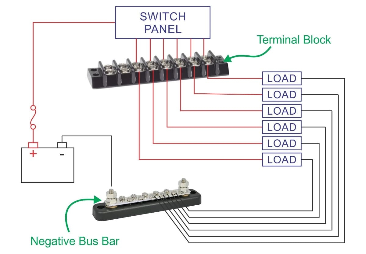
Marine Terminal Blocks 2 To 20 Circuits New Wire Marine
The image title is Marine Terminal Blocks 2 To 20 Circuits New Wire Marine, features dimensions of width 1200 px and height 835 px, with a file size of 1200 x 835.
The images on this page, sourced from Google for educational purposes, may be copyrighted. If you own an image and wish its removal or have copyright concerns, please contact us. We aim to promptly address these issues in compliance with our copyright policy and DMCA standards. Your cooperation is appreciated.
Related Keywords to Terminal Block Wiring Diagram:
distribution block wiring diagram,terminal block circuit diagram,terminal block electrical diagram,terminal block wiring diagram,terminal block wiring diagram pdf

