Table of Contents
The Ultimate Guide to Tachometer Wiring Diagram
The Value of Tachometer Wiring Diagram
Tachometers play a crucial role in monitoring the speed of an engine, providing essential information for optimal performance. A well-connected tachometer ensures accurate readings, helping drivers maintain their vehicles effectively. Understanding the intricacies of tachometer wiring is essential for anyone looking to install or troubleshoot this vital component. In this comprehensive guide, we delve into the world of tachometer wiring diagrams, shedding light on the key aspects that drive efficiency and precision in engine monitoring.
Importance of Proper Wiring
Proper wiring is the backbone of any tachometer system, ensuring seamless communication between the engine and the instrument panel. A meticulously designed wiring diagram acts as a roadmap, guiding you through the intricate process of connecting various components to achieve optimal performance. Without a clear understanding of tachometer wiring, you risk inaccurate readings, malfunctions, or even damage to your vehicle’s engine. Let’s explore the essential elements of a tachometer wiring diagram to pave the way for a smooth installation process.
Components of a Tachometer Wiring Diagram
A typical tachometer wiring diagram consists of several key components, each playing a vital role in ensuring the accuracy and reliability of the system. These components may include:
Power Source: Connecting the tachometer to a stable power source is crucial for consistent performance.
Ignition Coil: This component facilitates communication between the engine and the tachometer, providing real-time speed readings.
Ground Connection: Proper grounding is essential to prevent electrical interference and ensure accurate readings.
Signal Wire: This wire carries the speed signal from the engine to the tachometer, enabling real-time monitoring.
Installation Steps
To successfully install a tachometer using a wiring diagram, follow these basic steps:
Locate the ignition coil and identify the signal wire.
Connect the power wire to a stable power source.
Establish a ground connection to prevent electrical interference.
Connect the signal wire to the tachometer input for speed readings.
Test the tachometer to ensure accurate readings.
Common Issues and Troubleshooting
Despite following the wiring diagram diligently, tachometer systems may encounter issues such as fluctuating readings or complete failure. Understanding common problems and their solutions is crucial for efficient troubleshooting. Some common issues include:
Loose connections: Tighten all connections to ensure stable communication.
Grounding issues: Check the ground connection for any faults or corrosion.
Signal interference: Shield signal wires to prevent interference from other electrical components.
By addressing these issues promptly and referring to the wiring diagram for guidance, you can resolve tachometer problems effectively and maintain the performance of your vehicle’s engine.
Related to Tachometer Wiring Diagram
- Switched Outlet Wiring Diagram
- Symbols For Wiring Diagrams
- T568b Wiring Diagram
- Tach Wiring Diagram
- Tachometer Diagram Wiring
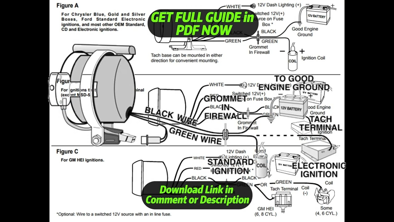
DIAGRAM Autometer Tach Wiring Diagram YouTube
The image title is DIAGRAM Autometer Tach Wiring Diagram YouTube, features dimensions of width 1280 px and height 720 px, with a file size of 1280 x 720 px. This image image/jpeg type visual are source from m.youtube.com.
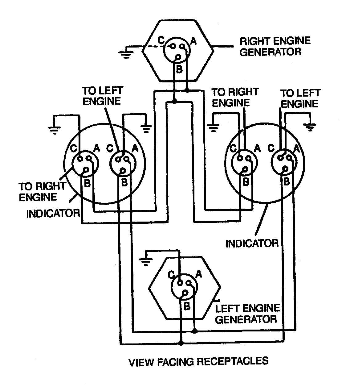
Figure 4 17 Dual Synchronous Rotor Tachometer Wiring Diagram
The image title is Figure 4 17 Dual Synchronous Rotor Tachometer Wiring Diagram, features dimensions of width 1136 px and height 1267 px, with a file size of 1136 x 1267 px. This image image/jpeg type visual are source from aviationmiscmanuals.tpub.com.
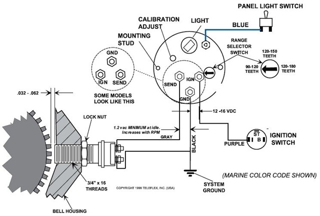
Magnetic Proximity Tachometer Tachometer Wiring Diagram Cruisers Sailing Photo Gallery
The image title is Magnetic Proximity Tachometer Tachometer Wiring Diagram Cruisers Sailing Photo Gallery, features dimensions of width 640 px and height 433 px, with a file size of 640 x 433. This image image/jpeg type visual are source from www.cruisersforum.com.
DIAGRAM Motorcycle Tachometer Wiring Diagram YouTube
The image title is DIAGRAM Motorcycle Tachometer Wiring Diagram YouTube, features dimensions of width 1280 px and height 720 px, with a file size of 1280 x 720. This image image/jpeg type visual are source from www.youtube.com.
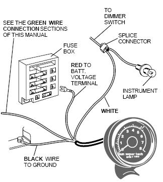
Ford Ranger Tachometer Install
The image title is Ford Ranger Tachometer Install, features dimensions of width 324 px and height 361 px, with a file size of 324 x 361. This image image/jpeg type visual are source from www.therangerstation.com
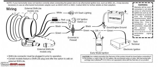
Pro Tachometer Wiring Diagram Tachometer Diagram Electrical Wiring Diagram
The image title is Pro Tachometer Wiring Diagram Tachometer Diagram Electrical Wiring Diagram, features dimensions of width 600 px and height 256 px, with a file size of 600 x 256. This image image/jpeg type visual are source from www.pinterest.com.
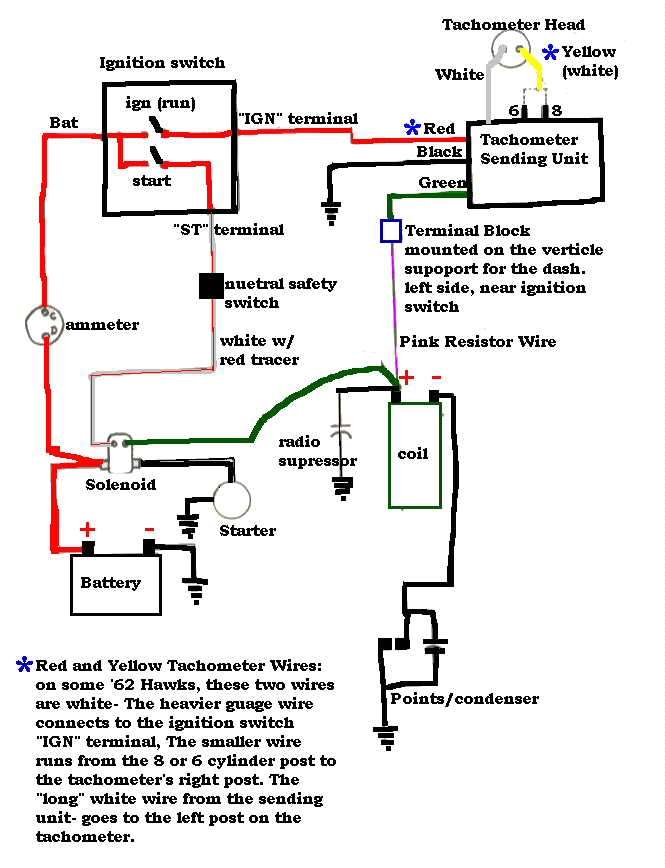
Official Website Of The BCOIE Chapter
The image title is Official Website Of The BCOIE Chapter, features dimensions of width 665 px and height 868 px, with a file size of 665 x 868. This image image/jpeg type visual are source from www.studebakersocal.com.
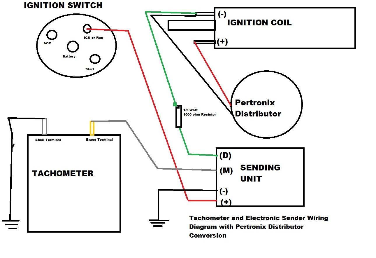
Classic Car Library
The image title is Classic Car Library, features dimensions of width 1290 px and height 884 px, with a file size of 1290 x 884.
The images on this page, sourced from Google for educational purposes, may be copyrighted. If you own an image and wish its removal or have copyright concerns, please contact us. We aim to promptly address these issues in compliance with our copyright policy and DMCA standards. Your cooperation is appreciated.
Related Keywords to Tachometer Wiring Diagram:
tach wiring diagram,tacho wiring diagram,tachometer wiring diagram,tachometer wiring diagram diesel,tachometer wiring diagram for motorcycle
