Table of Contents
The Ultimate Guide to Stator Wiring Diagrams
The Ultimate Guide to Stator Wiring Diagrams
When it comes to understanding the intricate workings of electrical systems, having a comprehensive stator wiring diagram at your disposal can make all the difference. This indispensable tool provides a detailed roadmap of the connections and configurations within a stator, offering invaluable insights into its functionality. Whether you’re a seasoned technician or a DIY enthusiast looking to troubleshoot electrical issues, delving into the world of stator wiring diagrams can unlock a wealth of knowledge and pave the way for seamless repairs and maintenance. Let’s embark on a journey to unravel the mysteries of stator wiring diagrams and discover the key components that power our electrical systems.
The Basics of Stator Wiring Diagrams
At the core of any electrical system lies the stator, a crucial component responsible for generating power through electromagnetic induction. A stator wiring diagram serves as a visual representation of the stator’s winding patterns, phase configurations, and connection points. By deciphering this diagram, technicians can trace the flow of current, identify potential faults, and ensure optimal performance of the electrical system. Understanding the basics of stator wiring diagrams is essential for diagnosing issues, making repairs, and maintaining the efficiency of machines and equipment.
Components of a Stator Wiring Diagram
A typical stator wiring diagram comprises several key components that form the building blocks of the electrical system. These components include:
Stator windings
Coil connections
Phase configurations
Terminal blocks
Ground connections
Each of these elements plays a critical role in the operation of the stator, and a thorough understanding of their interrelationships is essential for interpreting stator wiring diagrams accurately.
Interpreting Stator Wiring Diagrams
Navigating the complexities of a stator wiring diagram requires a keen eye for detail and a solid grasp of electrical principles. By following the lines, symbols, and annotations in the diagram, technicians can trace the path of current flow, identify potential short circuits or open circuits, and troubleshoot any issues that may arise. Interpreting stator wiring diagrams is a skill that can be honed through practice and experience, allowing technicians to diagnose problems efficiently and restore electrical systems to optimal performance.
Tips for Using Stator Wiring Diagrams
To make the most of stator wiring diagrams, consider the following tips:
Study the legend or key to understand the symbols and abbreviations used in the diagram.
Follow the flow of current from the power source to the load to identify potential points of failure.
Check for continuity using a multimeter to verify the integrity of connections and windings.
Consult the manufacturer’s specifications for the stator to ensure compliance with recommended practices.
By applying these tips and techniques, technicians can navigate stator wiring diagrams with confidence and precision, making informed decisions that enhance the reliability and efficiency of electrical systems.
Related to Stator Wiring Diagram
- Starter Motor Wiring Diagram
- Starter Relay Solenoid Wiring Diagram
- Starter Relay Wiring Diagram
- Starter Solenoid Wiring Diagram
- Starter Wiring Diagram
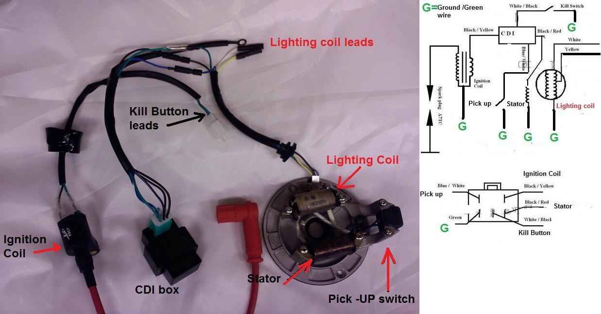
TBolt USA Tech Database TBolt USA LLC
The image title is TBolt USA Tech Database TBolt USA LLC, features dimensions of width 1238 px and height 648 px, with a file size of 1238 x 648 px. This image image/jpeg type visual are source from tboltusa.com.
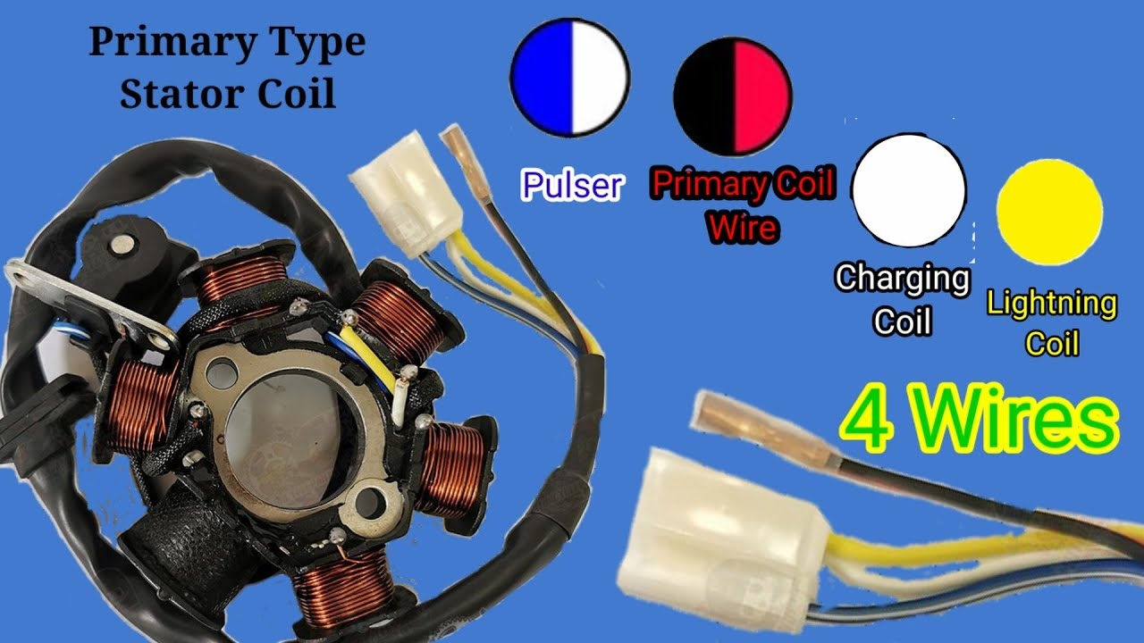
STATOR COIL Wiring Diagram YouTube
The image title is STATOR COIL Wiring Diagram YouTube, features dimensions of width 1280 px and height 720 px, with a file size of 1280 x 720 px. This image image/jpeg type visual are source from m.youtube.com.
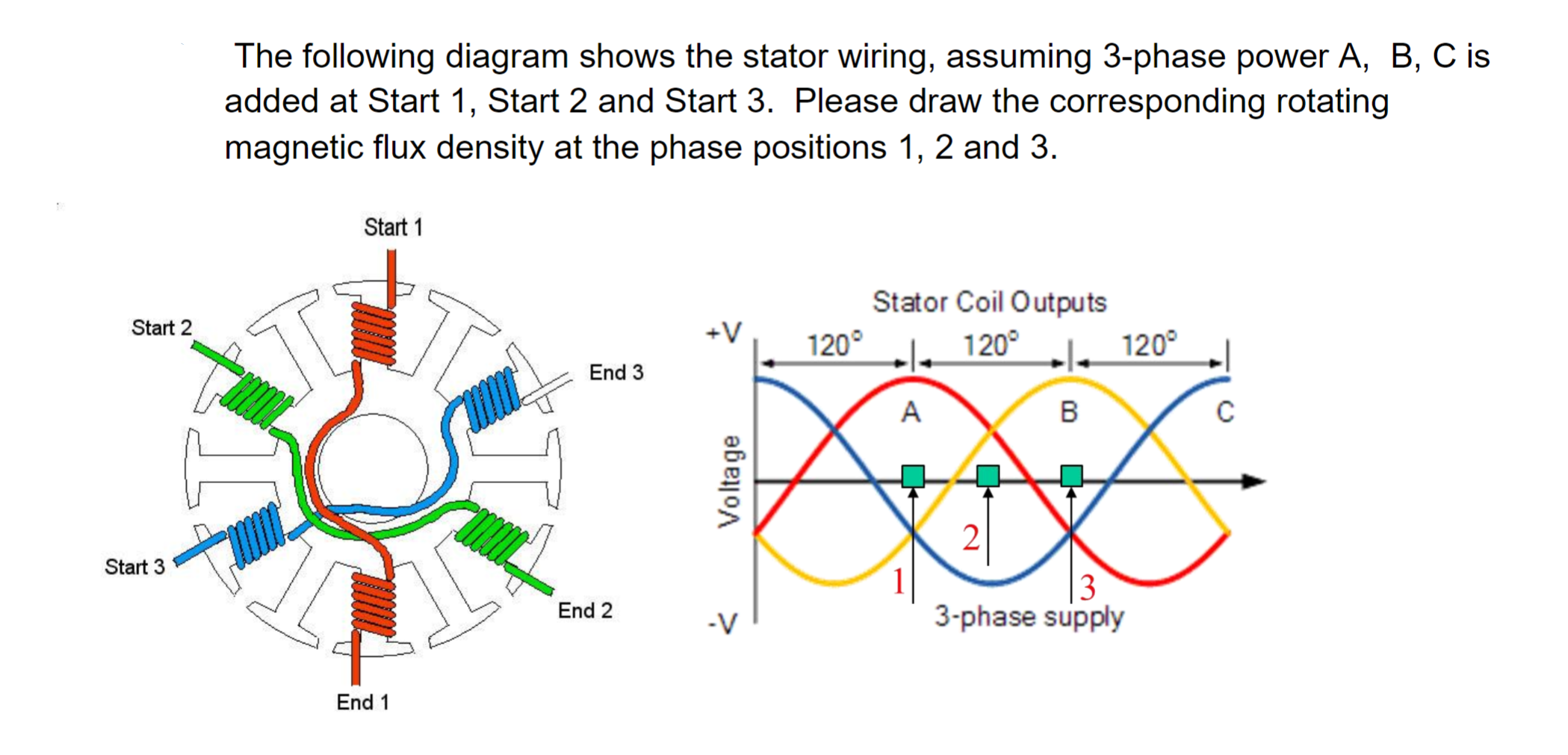
Solved The Following Diagram Shows The Stator Wiring Chegg
The image title is Solved The Following Diagram Shows The Stator Wiring Chegg, features dimensions of width 2099 px and height 1011 px, with a file size of 2099 x 1011. This image image/png type visual are source from www.chegg.com.
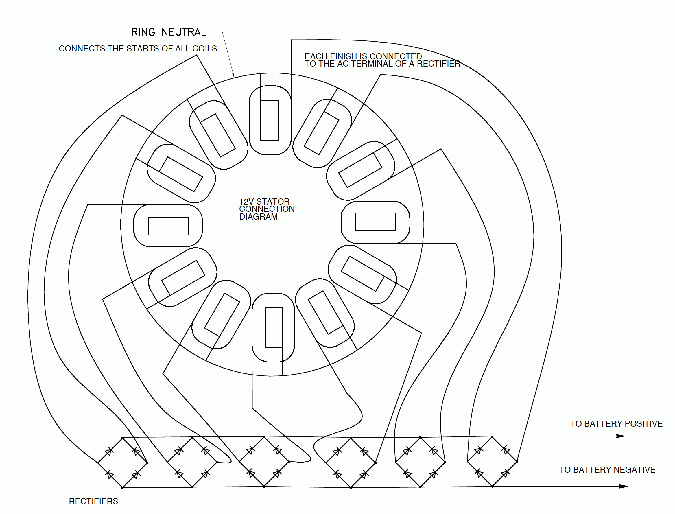
Wiring Up A 12 Volt Stator Hugh Piggott S Blog
The image title is Wiring Up A 12 Volt Stator Hugh Piggott S Blog, features dimensions of width 2334 px and height 1777 px, with a file size of 2334 x 1777. This image image/gif type visual are source from scoraigwind.co.uk.
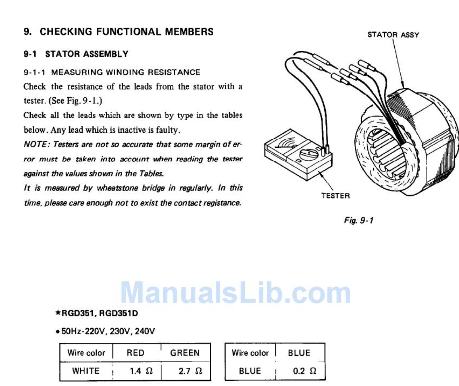
Generator Stator Wiring In Robin RGD351 Not Matching Manual Electrical Engineering Stack Exchange
The image title is Generator Stator Wiring In Robin RGD351 Not Matching Manual Electrical Engineering Stack Exchange, features dimensions of width 1549 px and height 1304 px, with a file size of 1549 x 1304. This image image/png type visual are source from electronics.stackexchange.com
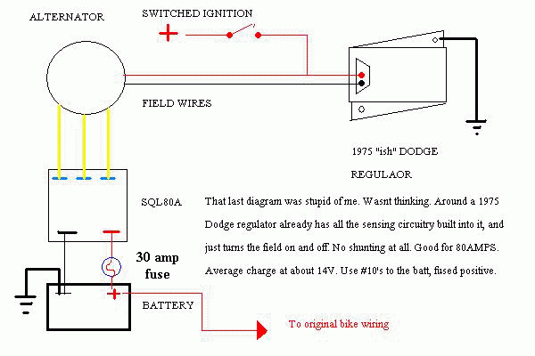
Five Wire Stator Setup
The image title is Five Wire Stator Setup, features dimensions of width 600 px and height 400 px, with a file size of 600 x 400. This image image/gif type visual are source from roadstercycle.com.
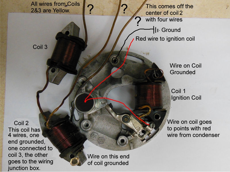
Modern Vespa Vespa Stator Wiring Blues
The image title is Modern Vespa Vespa Stator Wiring Blues, features dimensions of width 800 px and height 601 px, with a file size of 800 x 601. This image image/jpeg type visual are source from modernvespa.com.
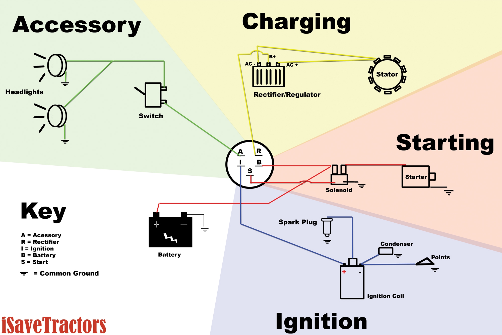
Basic Wiring Diagram For All Garden Tractors Using A Stator And Battery Ignition System ISaveTractors
The image title is Basic Wiring Diagram For All Garden Tractors Using A Stator And Battery Ignition System ISaveTractors, features dimensions of width 2000 px and height 1333 px, with a file size of 2000 x 1333.
The images on this page, sourced from Google for educational purposes, may be copyrighted. If you own an image and wish its removal or have copyright concerns, please contact us. We aim to promptly address these issues in compliance with our copyright policy and DMCA standards. Your cooperation is appreciated.
Related Keywords to Stator Wiring Diagram:
aerox stator wiring diagram,gy6 stator wiring diagram,motorcycle stator wiring diagram,stator coil wiring diagram,stator wiring diagram
