Table of Contents
The Value of Rev Counter Wiring Diagram
Rev counter wiring diagrams are an essential tool for anyone looking to understand the intricacies of their vehicle’s electrical system. Whether you are a seasoned automotive enthusiast or a novice DIY mechanic, having access to a detailed wiring diagram can make all the difference when it comes to troubleshooting electrical issues or modifying your vehicle’s wiring. By providing a visual representation of how various components are connected within the system, a rev counter wiring diagram offers invaluable insights into the inner workings of your vehicle’s electrical system.
Understanding the Basics
Before delving into the specifics of a rev counter wiring diagram, it is crucial to have a basic understanding of how it functions. The rev counter, also known as a tachometer, is an instrument that measures the rotational speed of the engine’s crankshaft in revolutions per minute (RPM). This information is vital for monitoring engine performance and ensuring that it operates within optimal parameters.
Components of a Rev Counter Wiring Diagram
A typical rev counter wiring diagram consists of various components that work together to provide accurate RPM readings. These components include the tachometer itself, the ignition coil, the distributor, and various sensors that monitor engine speed. By examining how these components are interconnected within the wiring diagram, you can gain a deeper understanding of how the entire system operates.
Benefits of Using a Rev Counter Wiring Diagram
- Identifying and troubleshooting electrical issues
- Modifying or upgrading the electrical system
- Understanding the relationship between different components
- Ensuring proper installation of aftermarket components
How to Interpret a Rev Counter Wiring Diagram
- Start by familiarizing yourself with the symbols and color codes used in the diagram.
- Trace the wiring connections from the tachometer to the various components in the system.
- Pay attention to any junctions, splices, or connectors that may affect the flow of current.
- Refer to the manufacturer’s guidelines or technical manuals for additional insights.
Conclusion
In conclusion, a rev counter wiring diagram is a valuable resource for anyone looking to gain a deeper understanding of their vehicle’s electrical system. By studying the connections between different components and tracing the flow of current within the system, you can troubleshoot issues more effectively, make informed modifications, and ensure that your vehicle operates smoothly. Whether you are a professional mechanic or a DIY enthusiast, having access to a detailed wiring diagram can make all the difference in maintaining and optimizing your vehicle’s electrical system.
Related to Rev Counter Wiring Diagram
- Residential Electric Meter Box Wiring Diagram
- Residential Electrical Outlet Wiring Diagram
- Residential Manual Transfer Switch Wiring Diagram
- Residential Sprinkler System Wiring Diagram
- Residential Wiring Diagram
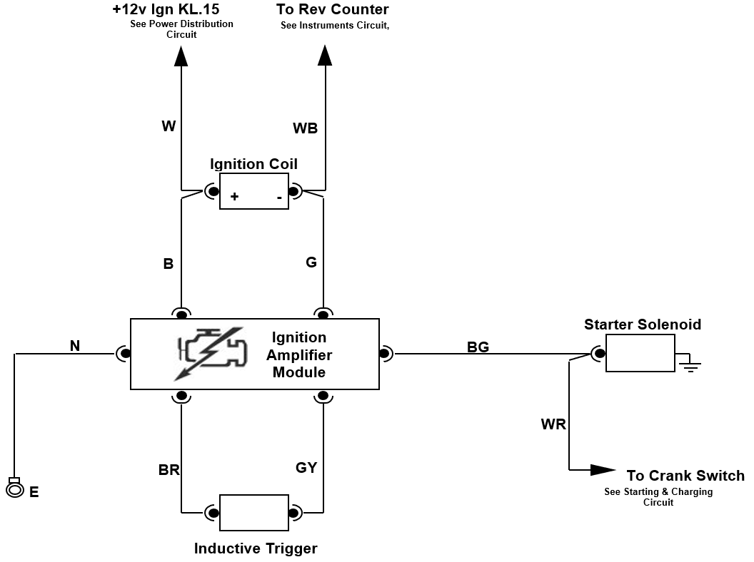
Rev Counter Wiring Electrics RHOCAR The UK Kit Car Club
The image title is Rev Counter Wiring Electrics RHOCAR The UK Kit Car Club, features dimensions of width 1056 px and height 788 px, with a file size of 1056 x 788 px. This image image/png type visual are source from www.rhocar.org.
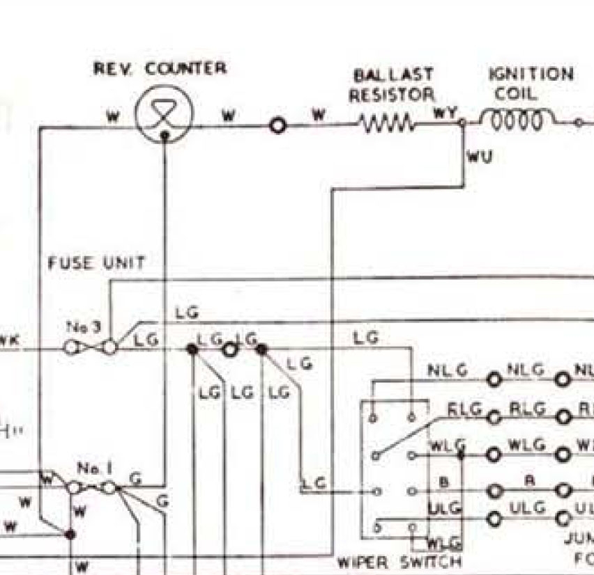
S1 Rev Counter Red Wire XJ Jag Lovers Forums
The image title is S1 Rev Counter Red Wire XJ Jag Lovers Forums, features dimensions of width 852 px and height 826 px, with a file size of 852 x 826 px. This image image/jpeg type visual are source from forums.jag-lovers.com.
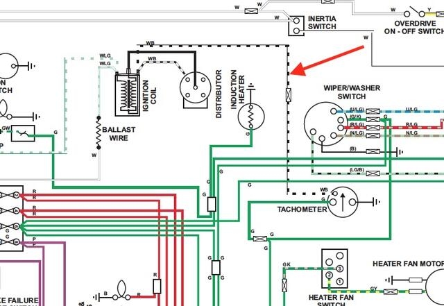
Tacho Replacement RVI RVC MGB GT Forum The MG Experience
The image title is Tacho Replacement RVI RVC MGB GT Forum The MG Experience, features dimensions of width 640 px and height 441 px, with a file size of 640 x 441. This image image/jpeg type visual are source from www.mgexp.com.
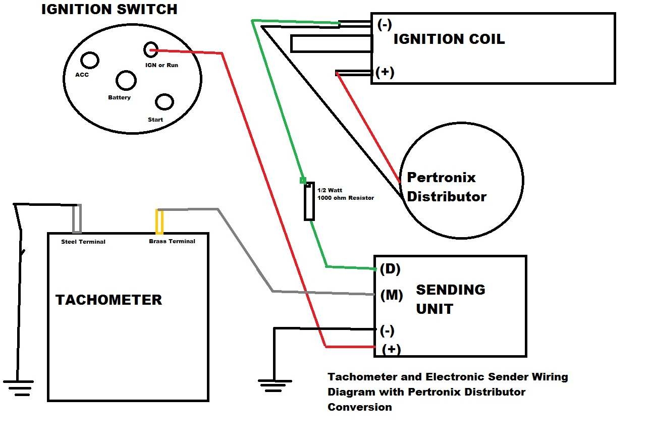
Classic Car Library
The image title is Classic Car Library, features dimensions of width 1290 px and height 884 px, with a file size of 1290 x 884. This image image/jpeg type visual are source from www.studebaker-info.org.
Gauge Experts Wiring An Old Unknown Electronic Rev Counter Electrical System The Triumph Sports Six Club Forum
The image title is Gauge Experts Wiring An Old Unknown Electronic Rev Counter Electrical System The Triumph Sports Six Club Forum, features dimensions of width 1229 px and height 922 px, with a file size of 1229 x 922. This image image/jpeg type visual are source from forum.tssc.org.uk
Official Website Of The BCOIE Chapter
The image title is Official Website Of The BCOIE Chapter, features dimensions of width 665 px and height 868 px, with a file size of 665 x 868. This image image/jpeg type visual are source from www.studebakersocal.com.
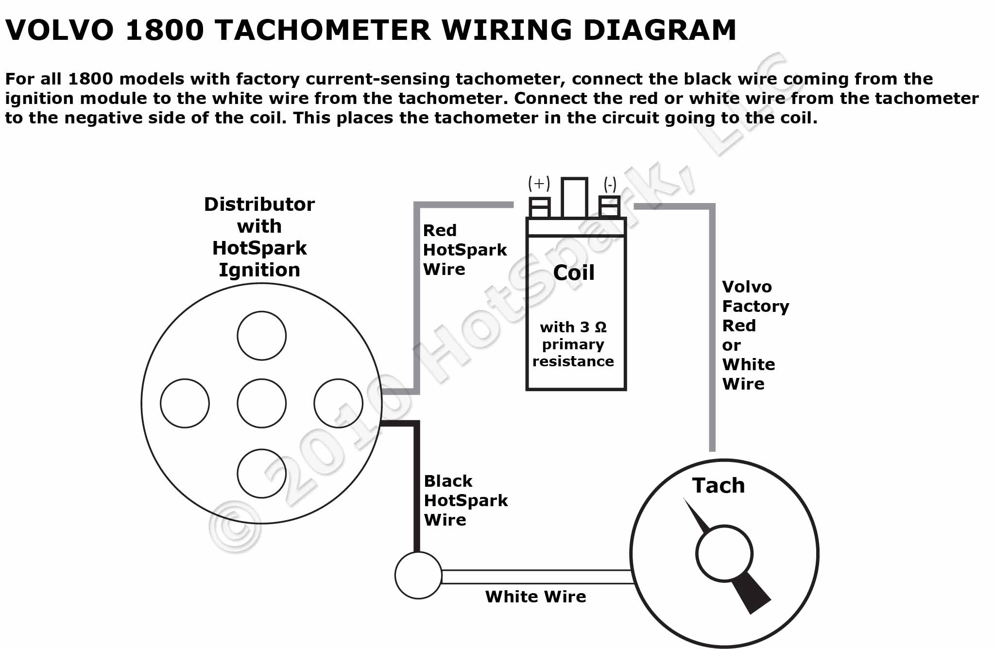
Volvo 1800 Tachometer Wiring Diagram With HotSpark Ignition Electronic Ignition Conversion Kit
The image title is Volvo 1800 Tachometer Wiring Diagram With HotSpark Ignition Electronic Ignition Conversion Kit, features dimensions of width 2046 px and height 1336 px, with a file size of 2046 x 1336. This image image/jpeg type visual are source from www.hot-spark.com.
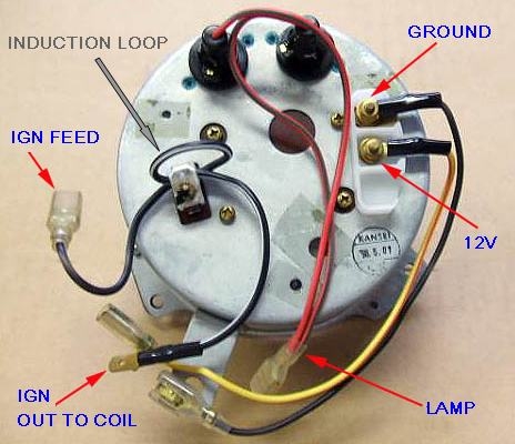
Wiring In Rev Counter Forum Main Forum Datsun 1200 Club
The image title is Wiring In Rev Counter Forum Main Forum Datsun 1200 Club, features dimensions of width 464 px and height 400 px, with a file size of 464 x 400.
The images on this page, sourced from Google for educational purposes, may be copyrighted. If you own an image and wish its removal or have copyright concerns, please contact us. We aim to promptly address these issues in compliance with our copyright policy and DMCA standards. Your cooperation is appreciated.
Related Keywords to Rev Counter Wiring Diagram:
rev counter circuit diagram,rev counter wiring diagram,rpm tachometer wiring diagram,smiths rev counter wiring diagram,vdo rev counter wiring diagram
