Table of Contents
The Importance of Pto Switch Wiring Diagram
The Value of Pto Switch Wiring Diagram
When it comes to maintaining and troubleshooting your PTO (Power Take-Off) system, having a clear and detailed wiring diagram is essential. A PTO switch wiring diagram serves as a roadmap that guides you through the electrical connections and components of your PTO system. It not only helps you understand how everything is interconnected but also simplifies the process of diagnosing issues and making repairs. Let’s delve into the world of PTO switch wiring diagrams to uncover their significance and how they play a crucial role in ensuring the optimal functionality of your equipment.
Understanding Pto Switch Wiring Diagram
A PTO switch wiring diagram is a visual representation of the electrical circuitry involved in operating your PTO system. It illustrates the connections between the PTO switch, relay, solenoid, and other components, providing a detailed overview of how power flows through the system. By studying the diagram, you can identify potential areas of concern, such as loose connections, faulty components, or miswiring, that may be causing your PTO system to malfunction.
The Benefits of Using Pto Switch Wiring Diagram
Facilitates troubleshooting by providing a clear roadmap of the electrical connections.
Aids in identifying and resolving issues efficiently, saving time and effort.
Enhances safety by ensuring proper wiring and preventing potential hazards.
Serves as a reference tool for maintenance and repair tasks, guiding you through the process step by step.
How to Interpret Pto Switch Wiring Diagram
Start by familiarizing yourself with the key components in the diagram, such as the PTO switch, relay, solenoid, and power source.
Follow the flow of power through the system, tracing the path from the PTO switch to the components it controls.
Note any junctions, connections, or terminals where potential issues may arise, such as loose wires or corroded terminals.
Refer to the diagram when troubleshooting or making repairs to ensure that all connections are properly established and functioning correctly.
Conclusion
In conclusion, a PTO switch wiring diagram is a valuable tool that can help you maintain, troubleshoot, and repair your PTO system effectively. By understanding the electrical layout of your PTO system and using the diagram as a reference, you can ensure that your equipment operates smoothly and safely. Whether you’re a seasoned technician or a novice DIY enthusiast, having a detailed wiring diagram at your disposal can make all the difference in keeping your PTO system in top condition.
Related to Pto Switch Wiring Diagram
- Predator 212 Wiring Diagram
- Predator 670 Wiring Diagram
- Pressure Switch For Air Compressor Wiring Diagram
- Pressure Switch Wiring Diagram
- Pressure Switch Wiring Diagram Air Compressor
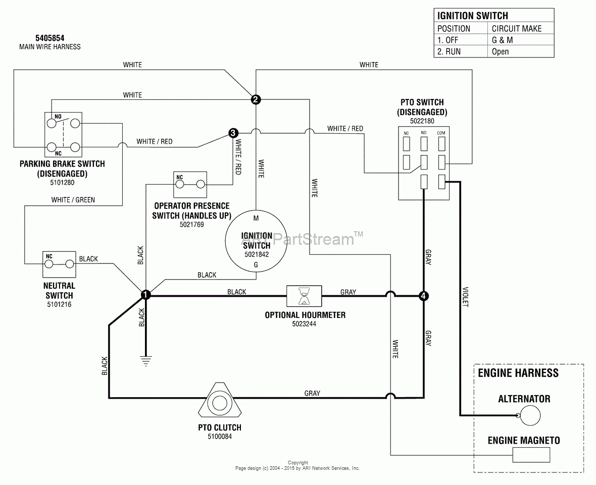
Snapper Pro 5900964 SW30KAV1848 48 Walk Behind Mower Parts Diagram For Electrical Schematic PTO Clutch Circuit Manual Start Kawasaki
The image title is Snapper Pro 5900964 SW30KAV1848 48 Walk Behind Mower Parts Diagram For Electrical Schematic PTO Clutch Circuit Manual Start Kawasaki, features dimensions of width 1180 px and height 961 px, with a file size of 1180 x 961 px. This image image/gif type visual are source from www.jackssmallengines.com.
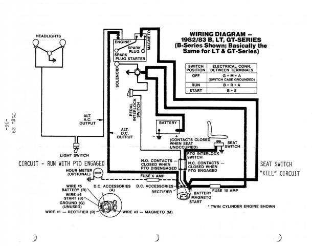
PTO Interlock Stop Switch Wheel Horse Electrical RedSquare Wheel Horse Forum
The image title is PTO Interlock Stop Switch Wheel Horse Electrical RedSquare Wheel Horse Forum, features dimensions of width 610 px and height 480 px, with a file size of 610 x 480 px. This image image/jpeg type visual are source from www.wheelhorseforum.com.
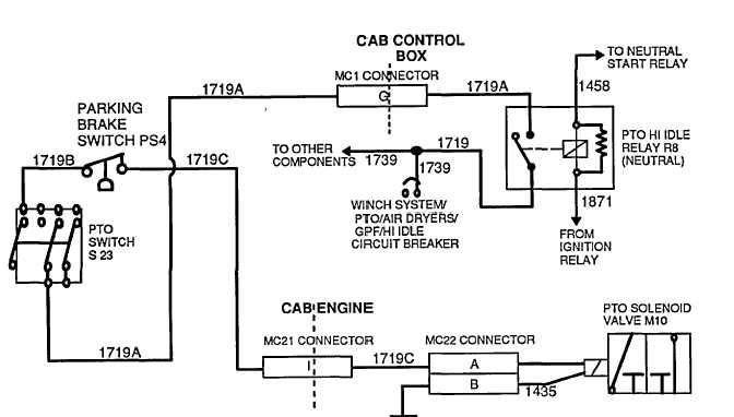
PTO WIRING DIAGRAM
The image title is PTO WIRING DIAGRAM, features dimensions of width 672 px and height 382 px, with a file size of 672 x 382. This image image/jpeg type visual are source from constructiontractors.tpub.com.
580 PTO Wiring IH Cub Cadet Tractor Forum
The image title is 580 PTO Wiring IH Cub Cadet Tractor Forum, features dimensions of width 482 px and height 422 px, with a file size of 482 x 422. This image image/jpeg type visual are source from www.ihcubcadet.com.
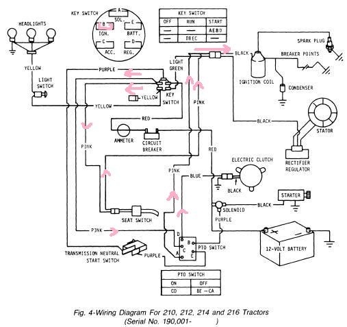
Electric Pto Problem John Deere Tractor Forum John Deere Electrical Diagram John Deere Tractors
The image title is Electric Pto Problem John Deere Tractor Forum John Deere Electrical Diagram John Deere Tractors, features dimensions of width 507 px and height 477 px, with a file size of 507 x 477. This image image/jpeg type visual are source from www.pinterest.com
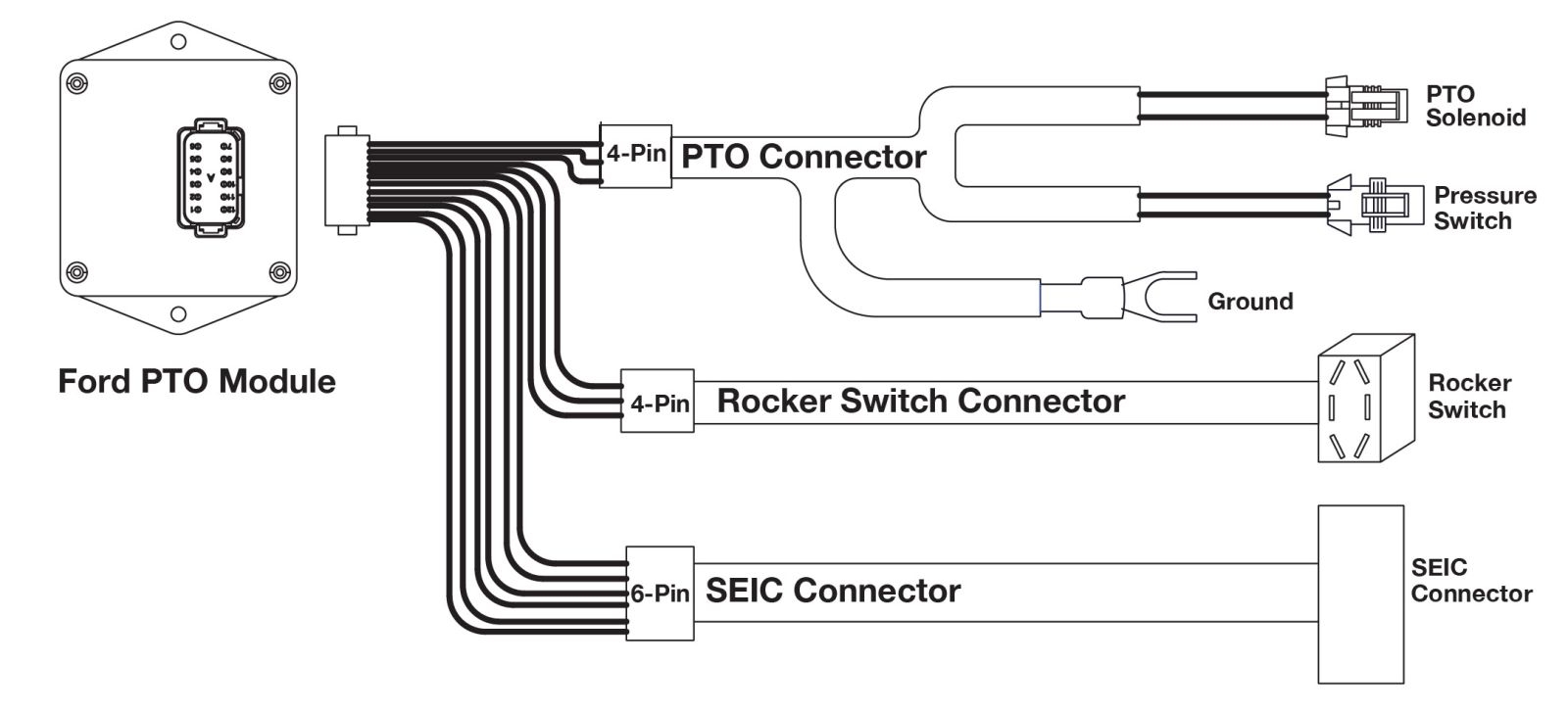
How To Install And Program The PTO RPM Module On Ford Trucks
The image title is How To Install And Program The PTO RPM Module On Ford Trucks, features dimensions of width 1600 px and height 728 px, with a file size of 1600 x 728. This image image/jpeg type visual are source from www.munciepower.com.
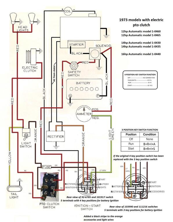
Electric Clutch Switch Wiring Wheel Horse Electrical RedSquare Wheel Horse Forum
The image title is Electric Clutch Switch Wiring Wheel Horse Electrical RedSquare Wheel Horse Forum, features dimensions of width 597 px and height 768 px, with a file size of 597 x 768. This image image/jpeg type visual are source from www.wheelhorseforum.com.
SWZ Hydro Drive Walk Behind Color Wiring Diagram SCAGTech
The image title is SWZ Hydro Drive Walk Behind Color Wiring Diagram SCAGTech, features dimensions of width 495 px and height 640 px, with a file size of 495 x 640.
The images on this page, sourced from Google for educational purposes, may be copyrighted. If you own an image and wish its removal or have copyright concerns, please contact us. We aim to promptly address these issues in compliance with our copyright policy and DMCA standards. Your cooperation is appreciated.
Related Keywords to Pto Switch Wiring Diagram:
chelsea pto switch wiring diagram,husqvarna pto switch wiring diagram,mower pto switch wiring diagram,muncie pto switch wiring diagram,pto switch wiring diagram
