Table of Contents
The Value of Limit Switch Wiring Diagram
Limit switches are essential components in industrial automation systems, providing a mechanism to detect the presence or absence of an object. These switches play a crucial role in ensuring the safety and efficiency of various processes. To understand the intricate wiring of limit switches, a detailed diagram is indispensable. A Limit Switch Wiring Diagram serves as a roadmap, guiding technicians and engineers through the intricate connections and configurations required for optimal performance.
Understanding Limit Switches
Before delving into the wiring diagram, it is essential to grasp the fundamentals of limit switches. These devices are electromechanical switches that are activated by the motion of an object, triggering a response based on predefined limits. Limit switches are commonly used in industrial machinery, robotics, and automated systems to control motion, position, and safety functions.
Components of a Limit Switch
A typical limit switch consists of several key components, including:
- Actuator: The part of the switch that is physically activated by the object’s motion.
- Contact Block: Contains the electrical contacts that open or close based on the actuator’s position.
- Housing: Encases the internal components and provides protection from environmental factors.
Importance of Wiring Diagrams
A well-designed wiring diagram is crucial for installing, troubleshooting, and maintaining limit switches. It provides a visual representation of how the components are interconnected, helping technicians identify the correct wiring configuration and ensure proper functionality. Without a clear and detailed diagram, the risk of errors during installation or repair increases significantly.
Benefits of Using a Wiring Diagram
By referring to a comprehensive wiring diagram, technicians can:
- Ensure accurate connections between components.
- Troubleshoot issues effectively by tracing the electrical pathways.
- Minimize downtime by quickly identifying and resolving wiring problems.
Creating a Limit Switch Wiring Diagram
When creating a wiring diagram for limit switches, attention to detail is paramount. The diagram should clearly depict the connections between the power source, limit switches, and other components in the system. Each wire’s color coding, terminal designations, and connection points should be accurately represented to facilitate easy installation and maintenance.
Key Considerations for Wiring Diagrams
Some essential considerations when developing a limit switch wiring diagram include:
- Identifying the functions of each limit switch in the system.
- Labeling the terminals and wires for clarity.
- Including a legend or key to explain symbols and markings used in the diagram.
Conclusion
In conclusion, a well-crafted Limit Switch Wiring Diagram is a valuable tool for technicians and engineers working with industrial automation systems. By providing a clear visual guide to the wiring connections, these diagrams streamline installation, troubleshooting, and maintenance processes. Understanding the importance of wiring diagrams and adhering to best practices in diagram creation can enhance the efficiency and reliability of limit switch installations.
Related to Limit Switch Wiring Diagram
- Light Switch Wiring Diagram 3 Wires
- Light Wiring Diagram
- Lighting Contactor Wiring Diagram
- Lighting Wiring Diagram
- Lights Wiring Diagram
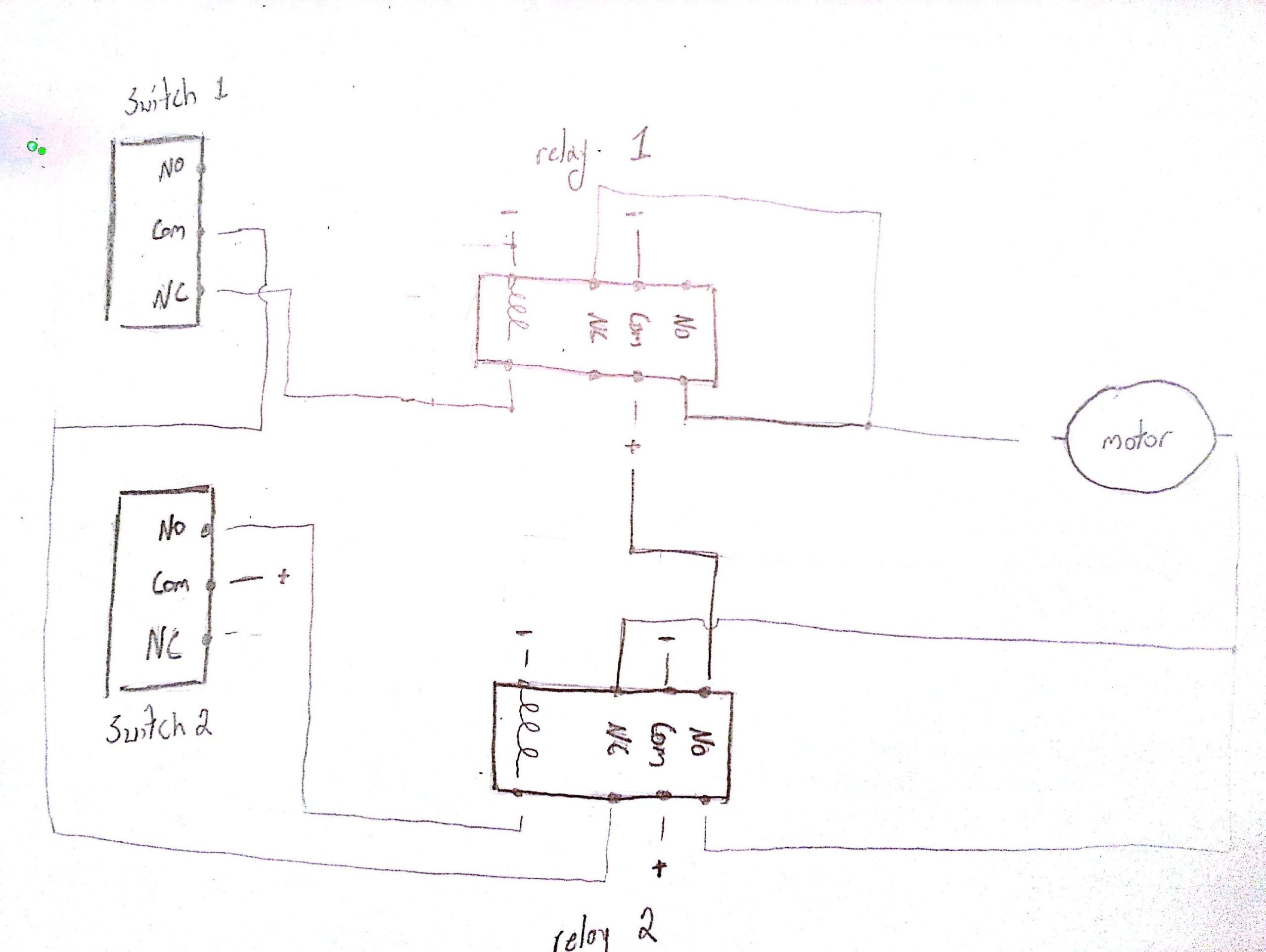
Relay Limit Switches To Control Motor Direction Electrical Engineering Stack Exchange
The image title is Relay Limit Switches To Control Motor Direction Electrical Engineering Stack Exchange, features dimensions of width 2560 px and height 1926 px, with a file size of 3244 x 2440 px. This image image/jpeg type visual are source from electronics.stackexchange.com.
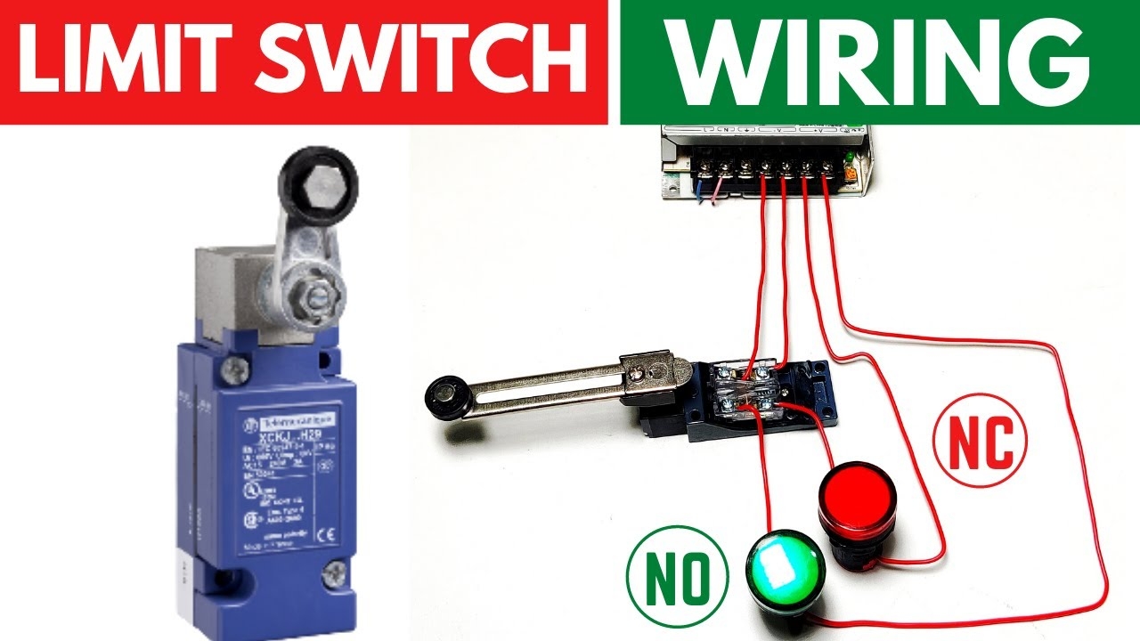
Limit Switch Connection Wiring With AC DC Load II Working Of Limit Switch YouTube
The image title is Limit Switch Connection Wiring With AC DC Load II Working Of Limit Switch YouTube, features dimensions of width 1280 px and height 720 px, with a file size of 1280 x 720 px. This image image/jpeg type visual are source from www.youtube.com.
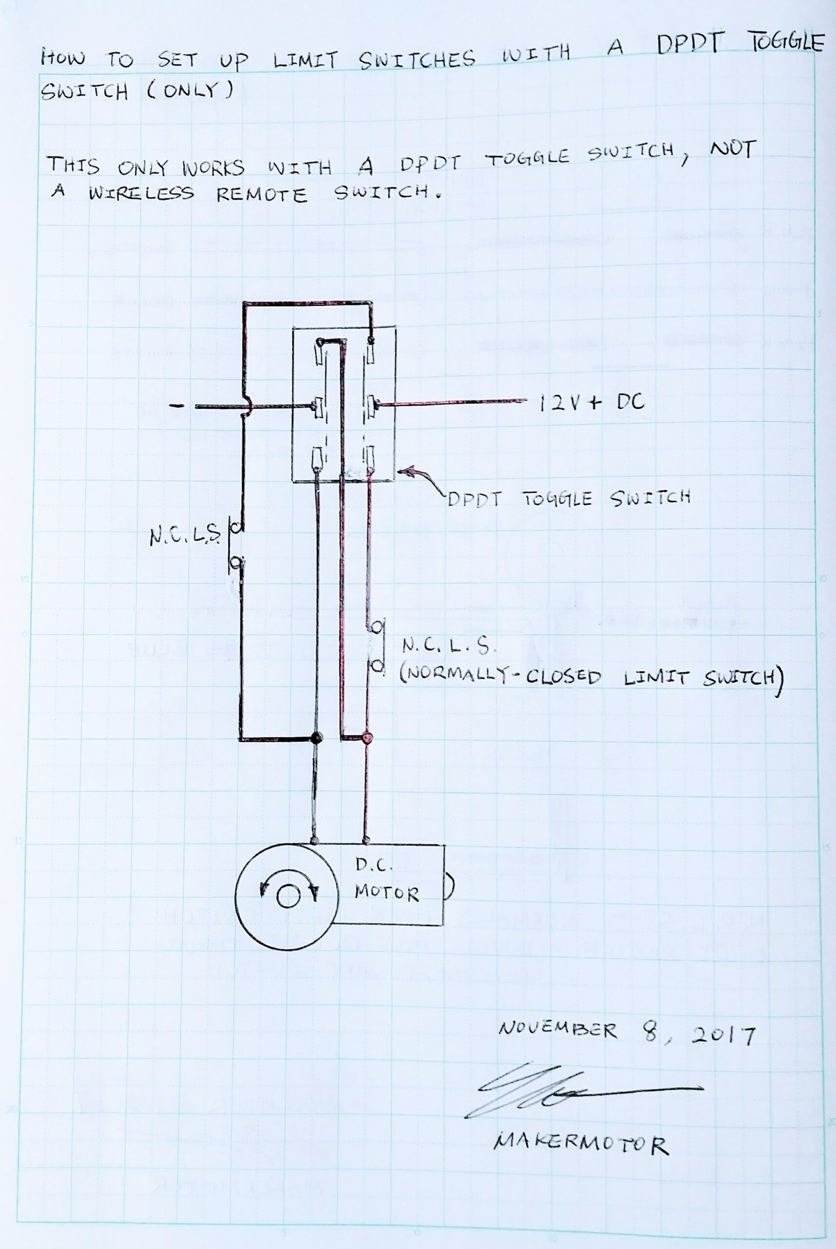
How To Set Up Limit Switches With A Wired DPDT Switch For Reverse Forward Controls Switch Circuit Design Switches
The image title is How To Set Up Limit Switches With A Wired DPDT Switch For Reverse Forward Controls Switch Circuit Design Switches, features dimensions of width 1714 px and height 2560 px, with a file size of 2080 x 3107. This image image/jpeg type visual are source from www.pinterest.com.
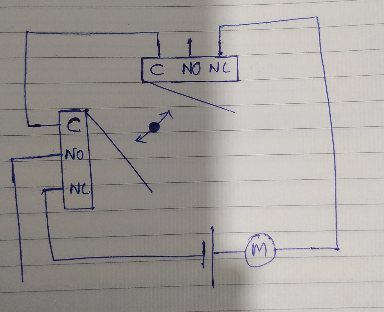
Relay Motor With Two Endstops Using Limit Switches Electrical Engineering Stack Exchange
The image title is Relay Motor With Two Endstops Using Limit Switches Electrical Engineering Stack Exchange, features dimensions of width 1325 px and height 1077 px, with a file size of 1325 x 1077. This image image/jpeg type visual are source from electronics.stackexchange.com.
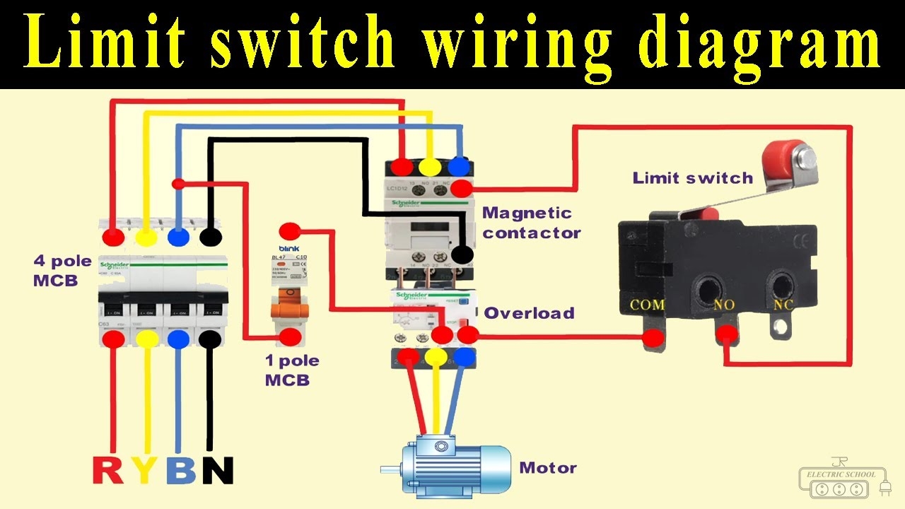
Limit Switch Connection In DOL Starter YouTube
The image title is Limit Switch Connection In DOL Starter YouTube, features dimensions of width 1280 px and height 720 px, with a file size of 1280 x 720. This image image/jpeg type visual are source from www.youtube.com
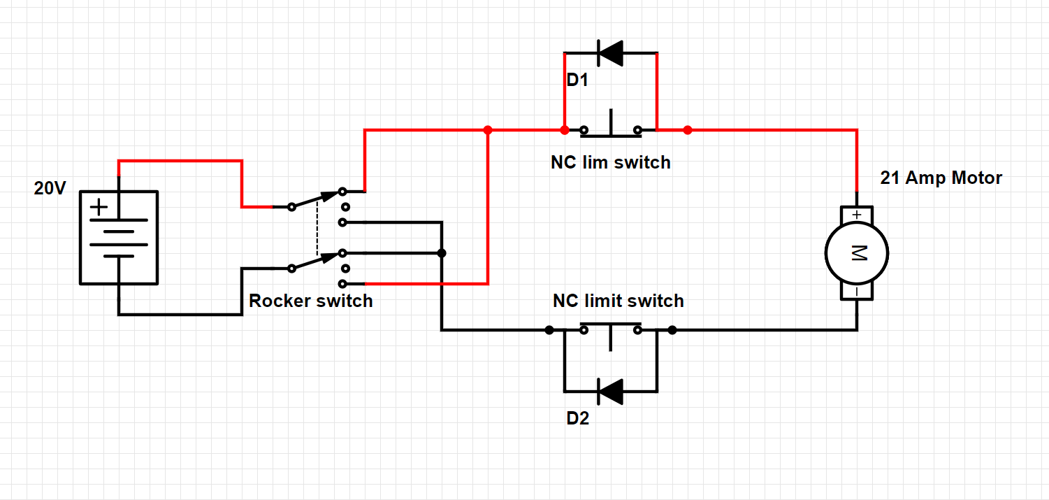
Wiring A Diode To A NC Limit Switch For Two Way Motor Control Switches Electronic Component And Engineering Solution Forum TechForum DigiKey
The image title is Wiring A Diode To A NC Limit Switch For Two Way Motor Control Switches Electronic Component And Engineering Solution Forum TechForum DigiKey, features dimensions of width 1501 px and height 715 px, with a file size of 1501 x 715. This image image/png type visual are source from forum.digikey.com.
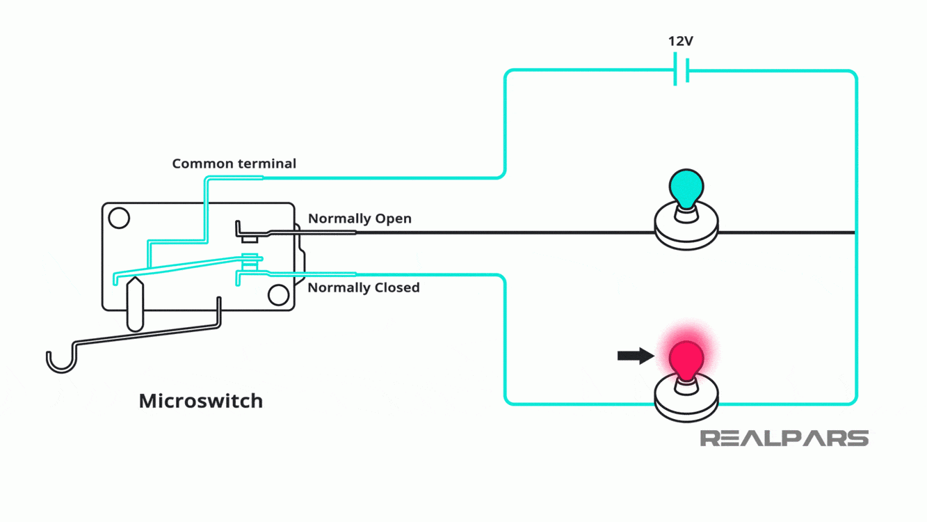
Limit Switch Explained Working Principles RealPars
The image title is Limit Switch Explained Working Principles RealPars, features dimensions of width 1333 px and height 750 px, with a file size of 1333 x 750. This image image/gif type visual are source from www.realpars.com.
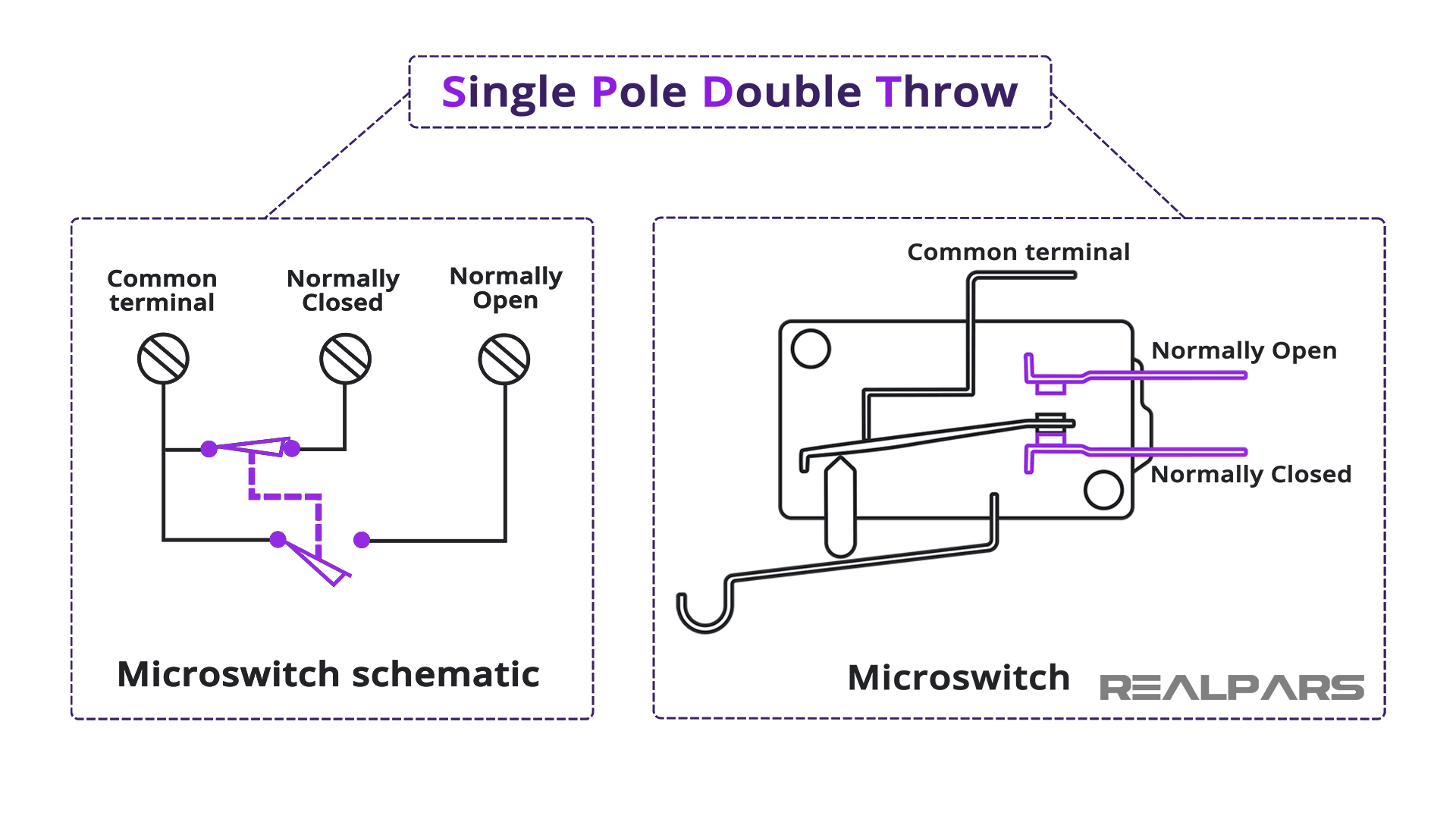
Limit Switch Explained Working Principles RealPars
The image title is Limit Switch Explained Working Principles RealPars, features dimensions of width 1920 px and height 1080 px, with a file size of 1920 x 1080.
The images on this page, sourced from Google for educational purposes, may be copyrighted. If you own an image and wish its removal or have copyright concerns, please contact us. We aim to promptly address these issues in compliance with our copyright policy and DMCA standards. Your cooperation is appreciated.
Related Keywords to Limit Switch Wiring Diagram:
limit switch connection diagram,limit switch wiring diagram,limit switch wiring diagram arduino,limit switch wiring diagram motor,limit switch wiring diagram symbols
