Table of Contents
The Significance of Isolated Ground Wiring Diagram
When it comes to electrical systems, safety and reliability are paramount. One crucial component that plays a significant role in ensuring a safe and efficient electrical setup is the isolated ground wiring diagram. This diagram acts as a blueprint for segregating the ground connection of sensitive equipment from the general ground, reducing the risk of electromagnetic interference and enhancing the overall performance of the system. Let’s delve into the world of isolated ground wiring diagrams and uncover their invaluable benefits.
Understanding the Concept of Isolated Ground
In essence, an isolated ground refers to a dedicated grounding path that is separate from the standard grounding system. By isolating the ground connection of specific equipment, such as computers, medical devices, or audiovisual equipment, from the general ground, any potential electrical noise or interference is minimized, resulting in cleaner power delivery and improved signal quality. The isolated ground wiring diagram outlines the precise configuration and connection points required to establish this isolated ground, ensuring optimal performance and safety.
Benefits of Using Isolated Ground Wiring Diagram
- Enhanced Equipment Performance: By reducing electromagnetic interference, isolated ground wiring diagrams help equipment operate at their optimal levels, leading to improved efficiency and longevity.
- Minimized Risk of Electrical Hazards: Isolating the ground connection of sensitive equipment lowers the chances of electrical faults, shocks, and fires, promoting a safer working environment.
- Compliance with Industry Standards: Many industries, such as healthcare and IT, mandate the use of isolated ground wiring to meet regulatory requirements and ensure system reliability.
Implementing Isolated Ground Wiring Diagram
The process of implementing an isolated ground wiring diagram involves meticulous planning and precise execution. It starts with identifying the equipment that requires isolation and determining the optimal routing of the dedicated ground path. Proper grounding techniques, such as using isolated ground receptacles and insulated grounding conductors, are crucial in maintaining the integrity of the isolated ground system. Regular testing and maintenance also play a vital role in ensuring the continued effectiveness of the isolated ground setup.
Conclusion
In the realm of electrical systems, the value of isolated ground wiring diagrams cannot be overstated. By isolating sensitive equipment from the general ground, these diagrams enhance performance, reduce risks, and promote compliance with industry standards. Whether you’re designing a new electrical setup or upgrading an existing system, incorporating isolated ground wiring diagrams is a wise investment in safety and reliability.
Related to Isolated Ground Wiring Diagram
- Intertherm Electric Furnace Wiring Diagram
- Intoxalock Wiring Diagram
- Inverter Wiring Diagram For Rv
- Invisible Fence Wiring Diagram
- Ip Camera Pinout Wiring Diagram
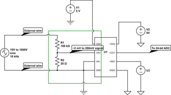
Opto Isolator Which Isolated Ground Should I Use For An RF Can Shield Over An Optically Isolating Component Electrical Engineering Stack Exchange
The image title is Opto Isolator Which Isolated Ground Should I Use For An RF Can Shield Over An Optically Isolating Component Electrical Engineering Stack Exchange, features dimensions of width 600 px and height 334 px, with a file size of 600 x 334 px. This image image/png type visual are source from electronics.stackexchange.com.
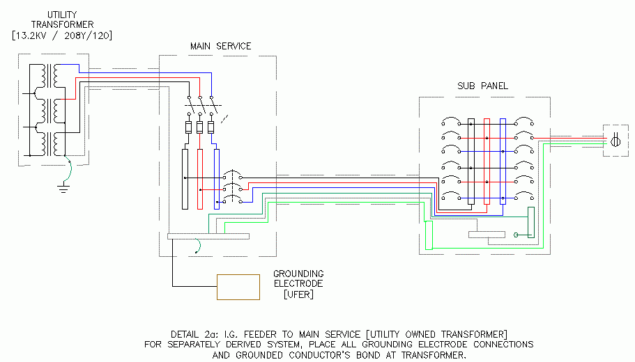
Isolated Ground ECN Electrical Forums
The image title is Isolated Ground ECN Electrical Forums, features dimensions of width 911 px and height 520 px, with a file size of 911 x 520 px. This image image/gif type visual are source from www.electrical-contractor.net.
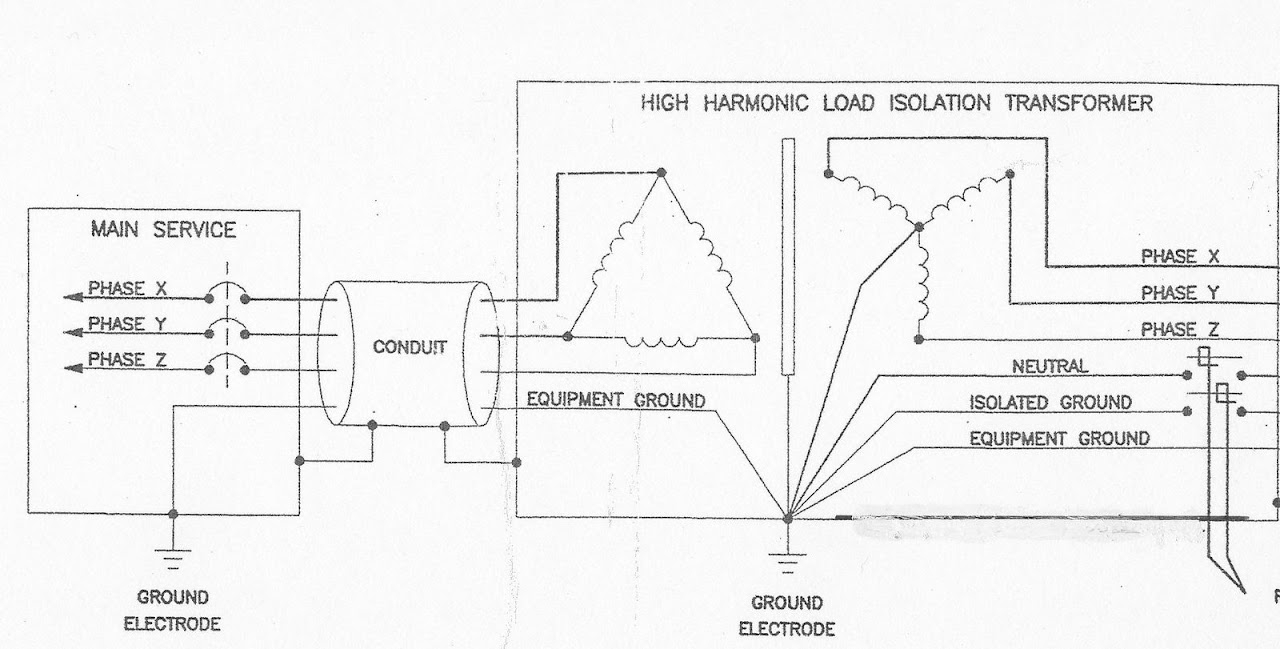
Isolated Ground Information By Electrical Professionals For Electrical Professionals
The image title is Isolated Ground Information By Electrical Professionals For Electrical Professionals, features dimensions of width 1280 px and height 649 px, with a file size of 1280 x 649. This image image/jpeg type visual are source from forums.mikeholt.com.
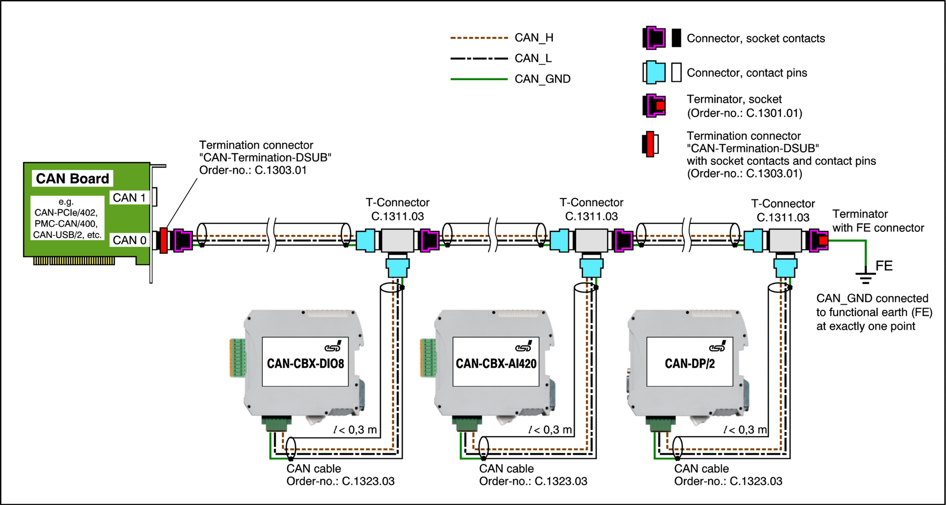
Professional Wiring Of Galvanically Isolated CAN Networks
The image title is Professional Wiring Of Galvanically Isolated CAN Networks, features dimensions of width 1920 px and height 1026 px, with a file size of 1920 x 1026. This image image/png type visual are source from esd.eu.
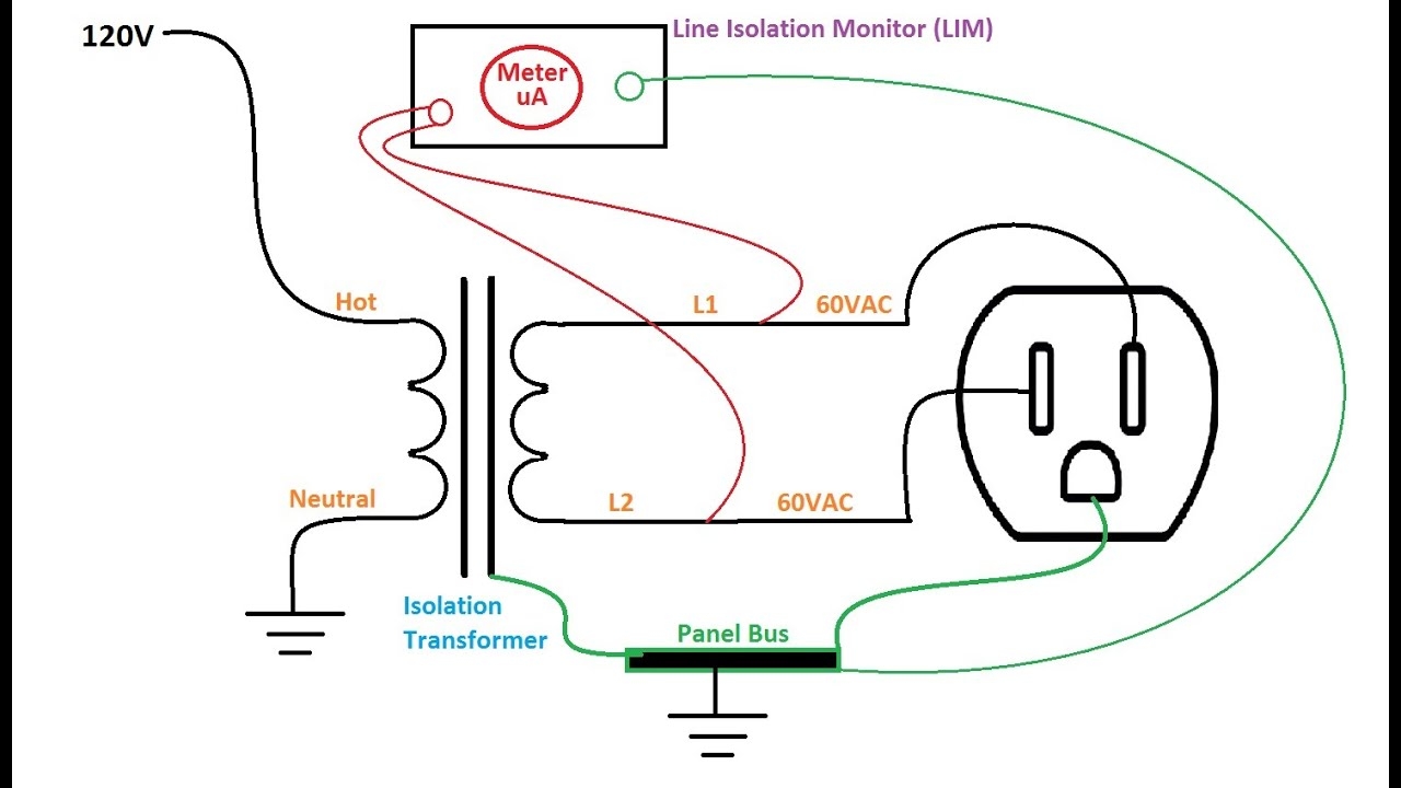
Isolated Electrical Systems LIM YouTube
The image title is Isolated Electrical Systems LIM YouTube, features dimensions of width 1280 px and height 720 px, with a file size of 1280 x 720. This image image/jpeg type visual are source from m.youtube.com
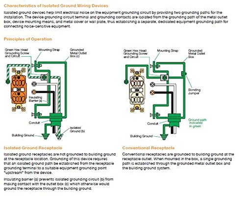
Amazon Bryant Electric CR15IG NEMA 5 15R 15 Amp 125V Commercial Specification Grade Isolated Ground Straight Blade Duplex Receptacle With 2 Pole And 3 Wire Grounding Orange Everything Else
The image title is Amazon Bryant Electric CR15IG NEMA 5 15R 15 Amp 125V Commercial Specification Grade Isolated Ground Straight Blade Duplex Receptacle With 2 Pole And 3 Wire Grounding Orange Everything Else, features dimensions of width 500 px and height 410 px, with a file size of 500 x 410. This image image/jpeg type visual are source from www.amazon.com.
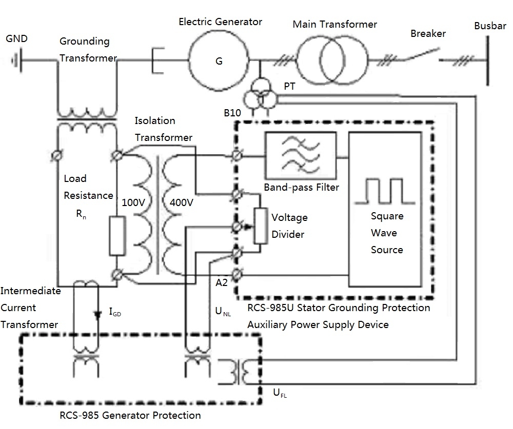
How To Wire Install Isolation Transformer ATO
The image title is How To Wire Install Isolation Transformer ATO, features dimensions of width 1000 px and height 837 px, with a file size of 1000 x 837. This image image/jpeg type visual are source from www.ato.com.
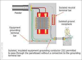
Isolated Grounding Receptacle Circuits Got Clean Grounds Or Dirty Grounds Receptacles Circuit Cleaning
The image title is Isolated Grounding Receptacle Circuits Got Clean Grounds Or Dirty Grounds Receptacles Circuit Cleaning, features dimensions of width 336 px and height 246 px, with a file size of 336 x 246.
The images on this page, sourced from Google for educational purposes, may be copyrighted. If you own an image and wish its removal or have copyright concerns, please contact us. We aim to promptly address these issues in compliance with our copyright policy and DMCA standards. Your cooperation is appreciated.
Related Keywords to Isolated Ground Wiring Diagram:
isolated ground circuit diagram,isolated ground panel wiring diagram,isolated ground system wiring diagram,isolated ground transformer wiring diagram,isolated ground wiring diagram
