Table of Contents
The Ultimate Guide to GM Maf Sensor Wiring Diagram
The Ultimate Guide to GM Maf Sensor Wiring Diagram
Are you looking to understand the intricacies of GM Maf Sensor Wiring Diagram? Look no further, as we delve into the essential details of this crucial component in your vehicle’s engine system. Whether you’re a seasoned mechanic or a DIY enthusiast, knowing how to navigate the wiring diagram of your GM Maf Sensor can save you time and money in diagnosing and fixing issues. Let’s explore the world of GM Maf Sensor Wiring Diagram and uncover its importance in your vehicle’s performance.
The Basics of GM Maf Sensor Wiring Diagram
The GM Maf Sensor, short for Mass Air Flow Sensor, plays a vital role in monitoring the amount of air entering the engine. This data is crucial for the engine control unit (ECU) to adjust fuel injection and optimize engine performance. The wiring diagram of the GM Maf Sensor illustrates the connections between the sensor and the ECU, providing a roadmap for troubleshooting and diagnosing issues.
Understanding the Components
Before delving into the wiring diagram, it’s essential to understand the components of the GM Maf Sensor. The sensor consists of a heated wire that measures the airflow, a thermistor that monitors the temperature, and a housing that protects the sensitive components. Each part plays a critical role in ensuring accurate data transmission to the ECU.
Interpreting the Wiring Diagram
The GM Maf Sensor Wiring Diagram outlines the electrical connections between the sensor and the ECU. It includes color-coded wires, pin configurations, and sensor locations to help you identify potential issues and make necessary repairs. By understanding the diagram, you can pinpoint faulty connections, damaged wires, or sensor malfunctions that may be affecting your engine performance.
Diagnostic Tips for GM Maf Sensor
When troubleshooting issues with your GM Maf Sensor, following these diagnostic tips can help you identify and resolve problems efficiently:
Check for loose or damaged wiring connections
Inspect the sensor for debris or dirt buildup
Use a multimeter to test the sensor’s voltage output
Verify the sensor’s resistance values against specifications
Common Problems and Solutions
Some common issues with GM Maf Sensors include erratic readings, poor engine performance, and engine stalling. Here are some solutions to address these problems:
Clean the sensor with Maf Sensor cleaner to remove dirt and debris
Replace damaged wiring or connectors to ensure a secure connection
Calibrate the sensor according to manufacturer specifications
Update the ECU software to resolve compatibility issues
Conclusion
In conclusion, understanding the GM Maf Sensor Wiring Diagram is essential for maintaining your vehicle’s engine performance and diagnosing issues effectively. By familiarizing yourself with the components, interpreting the wiring diagram, and following diagnostic tips, you can ensure your GM Maf Sensor operates optimally. Remember to consult your vehicle’s manual and seek professional help if needed to address any complex issues with the sensor. Stay tuned for more insights into the world of automotive wiring diagrams!
Related to Gm Maf Sensor Wiring Diagram
- Gm Body Control Module Wiring Diagram
- Gm Bose Amp Wiring Diagram
- Gm Fuel Pump Wiring Harness Diagram
- Gm Headlight Switch Wiring Diagram
- Gm Ignition Switch Wiring Diagram
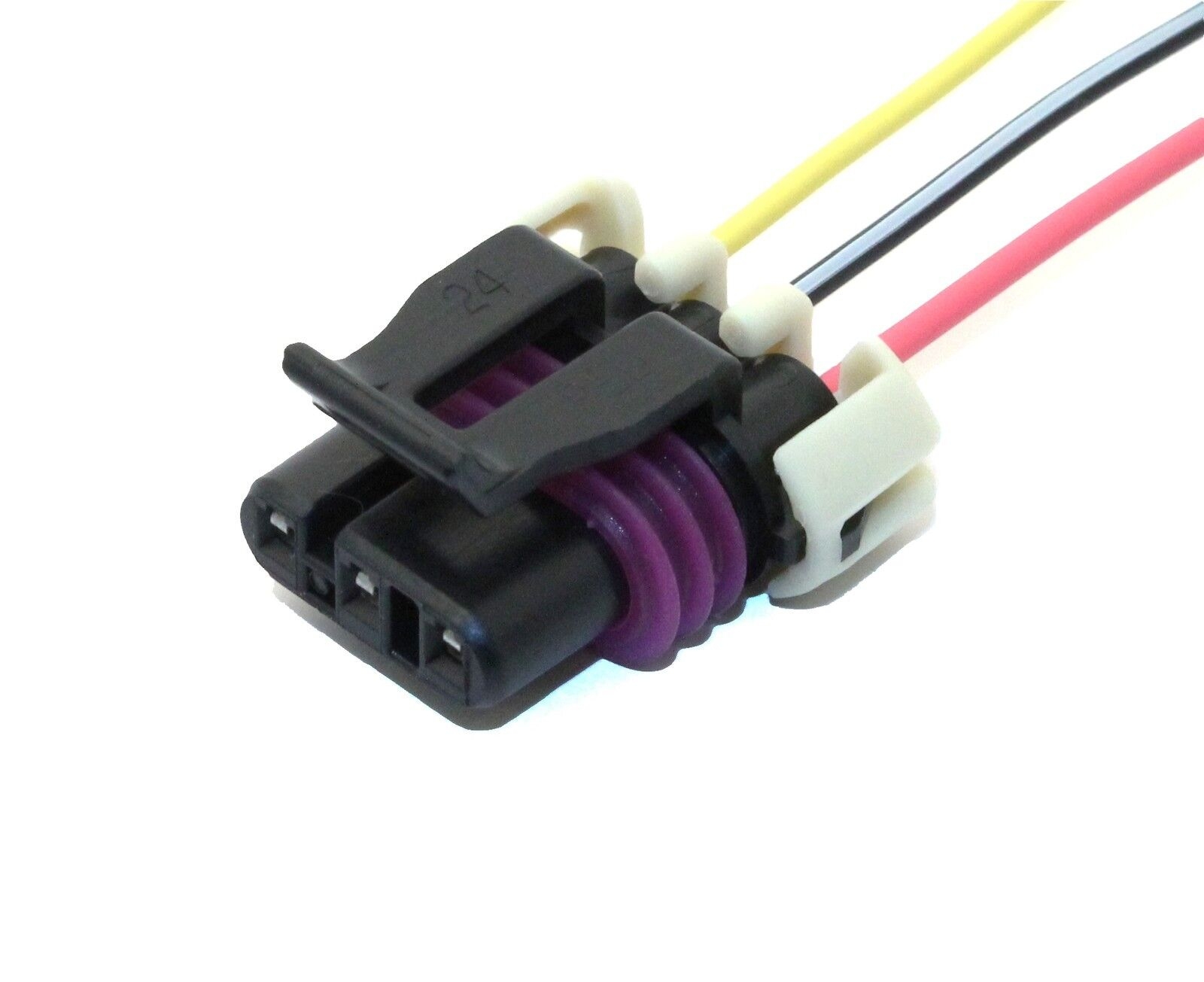
LS1 LT1 GM 3 Wire MAF Mass Air Flow Sensor Wiring Connector Pigtail EBay
The image title is LS1 LT1 GM 3 Wire MAF Mass Air Flow Sensor Wiring Connector Pigtail EBay, features dimensions of width 1600 px and height 1305 px, with a file size of 1600 x 1305 px. This image image/jpeg type visual are source from www.ebay.com.
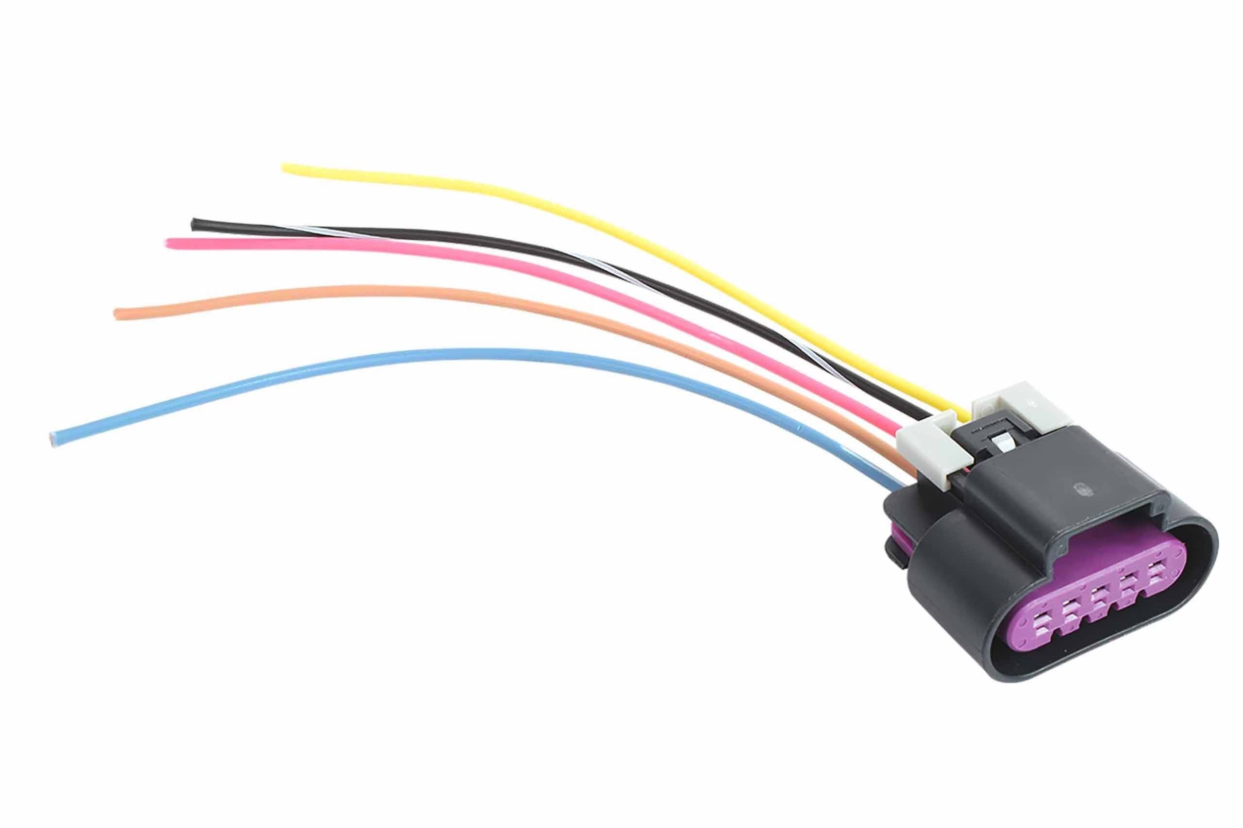
Amazon ICT BIllet LS3 Gen 4 Wire Pigtail Connector MAF 5 Wire Mass Air Flow IAT Intake Air Temperature Sensor Card Style Compatible With GM RPO Codes 6 2 L99 LS WPMAF43 Automotive
The image title is Amazon ICT BIllet LS3 Gen 4 Wire Pigtail Connector MAF 5 Wire Mass Air Flow IAT Intake Air Temperature Sensor Card Style Compatible With GM RPO Codes 6 2 L99 LS WPMAF43 Automotive, features dimensions of width 2560 px and height 1706 px, with a file size of 2560 x 1706 px. This image image/jpeg type visual are source from www.amazon.com.
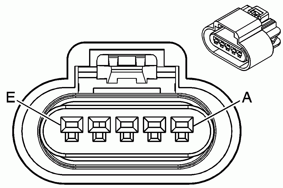
Mass Air Flow Sensor Pigtail Harness PGTL 003 Wiring Splices Pigtails Racetronix
The image title is Mass Air Flow Sensor Pigtail Harness PGTL 003 Wiring Splices Pigtails Racetronix, features dimensions of width 1131 px and height 752 px, with a file size of 1131 x 752. This image image/gif type visual are source from www.racetronix.biz.
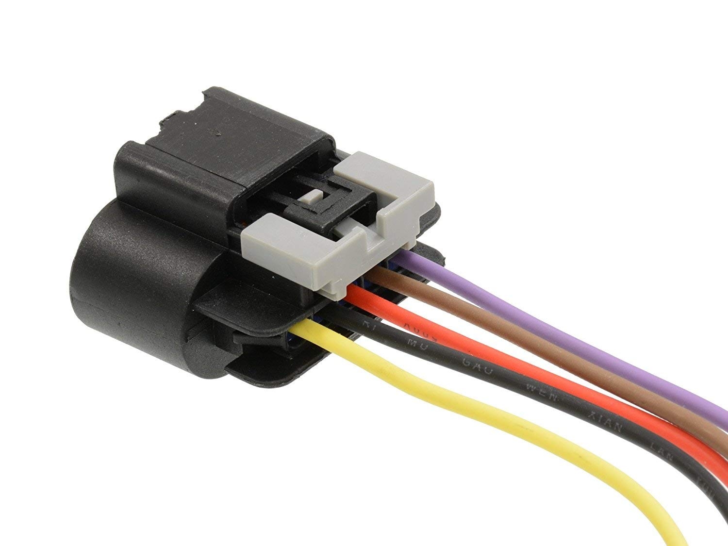
Amazon Michigan Motorsports 5 Wire Mass Air Flow Pigtail MAF For LS3 And LS7 Sensor Wire Harness Fitment Camaro Firebird Vehicles Automotive
The image title is Amazon Michigan Motorsports 5 Wire Mass Air Flow Pigtail MAF For LS3 And LS7 Sensor Wire Harness Fitment Camaro Firebird Vehicles Automotive, features dimensions of width 1500 px and height 1125 px, with a file size of 1500 x 1125. This image image/jpeg type visual are source from www.amazon.com.
MAF MASS AIR FLOW SENSOR ELECTRICAL CONNECTIONS THEORY AND TROUBLESHOOTING FROM WIRING DIAGRAM YouTube
The image title is MAF MASS AIR FLOW SENSOR ELECTRICAL CONNECTIONS THEORY AND TROUBLESHOOTING FROM WIRING DIAGRAM YouTube, features dimensions of width 1280 px and height 720 px, with a file size of 1280 x 720. This image image/jpeg type visual are source from m.youtube.com
Mass Air Flow Sensor Hot Wire Symptoms Of A Bad MAF Sensor YouTube Sensor Flow Mass
The image title is Mass Air Flow Sensor Hot Wire Symptoms Of A Bad MAF Sensor YouTube Sensor Flow Mass, features dimensions of width 1280 px and height 720 px, with a file size of 1280 x 720. This image image/jpeg type visual are source from www.pinterest.com.
Q A GMC Yukon Wiring Diagrams P0641 2002 2008 Models MAF Sensor GM 5 Wire 2003 2007 Denali
The image title is Q A GMC Yukon Wiring Diagrams P0641 2002 2008 Models MAF Sensor GM 5 Wire 2003 2007 Denali, features dimensions of width 2402 px and height 1691 px, with a file size of 2402 x 1691. This image image/gif type visual are source from www.justanswer.com.
GM 5 Wire MAF Sensor Wiring Diagram JustAnswer Q A
The image title is GM 5 Wire MAF Sensor Wiring Diagram JustAnswer Q A, features dimensions of width 960 px and height 958 px, with a file size of 960 x 958.
The images on this page, sourced from Google for educational purposes, may be copyrighted. If you own an image and wish its removal or have copyright concerns, please contact us. We aim to promptly address these issues in compliance with our copyright policy and DMCA standards. Your cooperation is appreciated.
Related Keywords to Gm Maf Sensor Wiring Diagram:
gm 5 wire maf sensor wiring diagram,gm maf sensor wiring diagram,gm mass air flow sensor wiring diagram,how do you reset the maf sensor,how to clean maf sensor gmc sierra


