Table of Contents
The Ultimate Guide to Fisher Plow Controller Wiring Diagram
The Ultimate Guide to Fisher Plow Controller Wiring Diagram
If you’re a seasoned snow plower or a newcomer to the world of plowing, having a comprehensive understanding of your Fisher plow controller wiring diagram is crucial. This diagram serves as the roadmap to effectively connect and control your plow’s functions, ensuring smooth operation and optimal performance. Whether you’re troubleshooting an issue, upgrading your system, or simply seeking to enhance your knowledge, delving into the intricacies of Fisher plow controller wiring diagrams can unlock a world of possibilities.
Understanding the Basics
Before delving into the specifics of Fisher plow controller wiring diagrams, it’s essential to grasp the foundational concepts. The wiring diagram outlines the electrical connections between the various components of your plow system, including the controller, solenoids, motors, and lights. By understanding these connections, you can troubleshoot issues, make modifications, or upgrade your system with ease.
Components of a Fisher Plow Controller Wiring Diagram
Controller
Solenoids
Motors
Lights
Benefits of Familiarizing Yourself with the Wiring Diagram
A thorough understanding of your Fisher plow controller wiring diagram offers a host of benefits. By familiarizing yourself with the diagram, you can:
Troubleshoot electrical issues efficiently
Make modifications or upgrades confidently
Ensure proper installation and operation of your plow system
Step-by-Step Guide to Reading a Fisher Plow Controller Wiring Diagram
To effectively navigate a Fisher plow controller wiring diagram, follow these steps:
Identify the key components of the diagram
Understand the symbols and abbreviations used
Trace the electrical connections between components
Refer to the legend or key for clarification
Common Issues and Solutions
Despite the reliability of Fisher plow systems, occasional electrical issues may arise. By referencing your wiring diagram and following a systematic troubleshooting approach, you can quickly diagnose and resolve common problems such as:
Intermittent controller functionality
Failed solenoids
Inoperative lights
Consulting Professional Resources
In some cases, complex electrical issues may require the expertise of a professional technician. By having a thorough understanding of your Fisher plow controller wiring diagram, you can effectively communicate with service providers and ensure a timely resolution to any problems.
Conclusion
Mastering the intricacies of your Fisher plow controller wiring diagram is a valuable skill that can enhance your plowing experience and empower you to tackle electrical challenges with confidence. By following the steps outlined in this guide and leveraging the insights provided, you can navigate your wiring diagram with ease and optimize the performance of your plow system.
Related to Fisher Plow Controller Wiring Diagram
- Fender Wiring Diagrams
- Feniex 4200 Mini Wiring Diagram
- Fire Alarm Wiring Diagram
- Firing Order 5.7 Hemi Spark Plug Wiring Diagram
- Fisher Minute Mount 2 Wiring Diagram
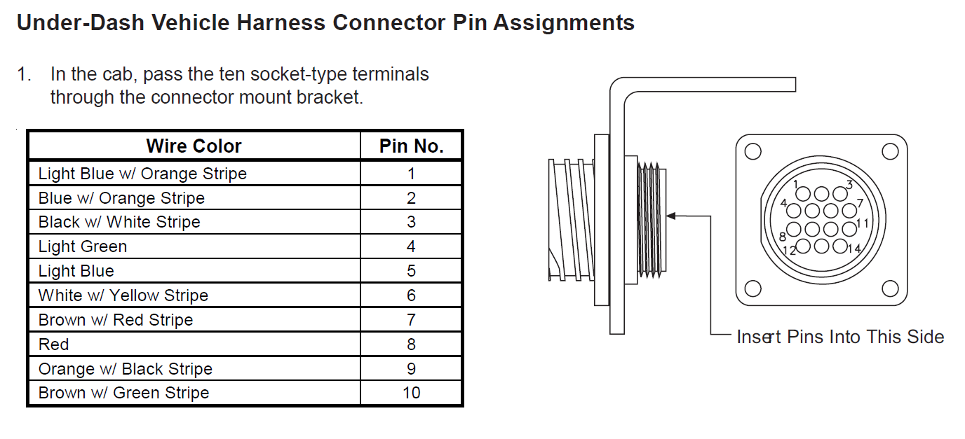
26346 Western Fisher Isolation Module Control Harness
The image title is 26346 Western Fisher Isolation Module Control Harness, features dimensions of width 1376 px and height 627 px, with a file size of 1376 x 627 px. This image image/png type visual are source from www.storksplows.com.
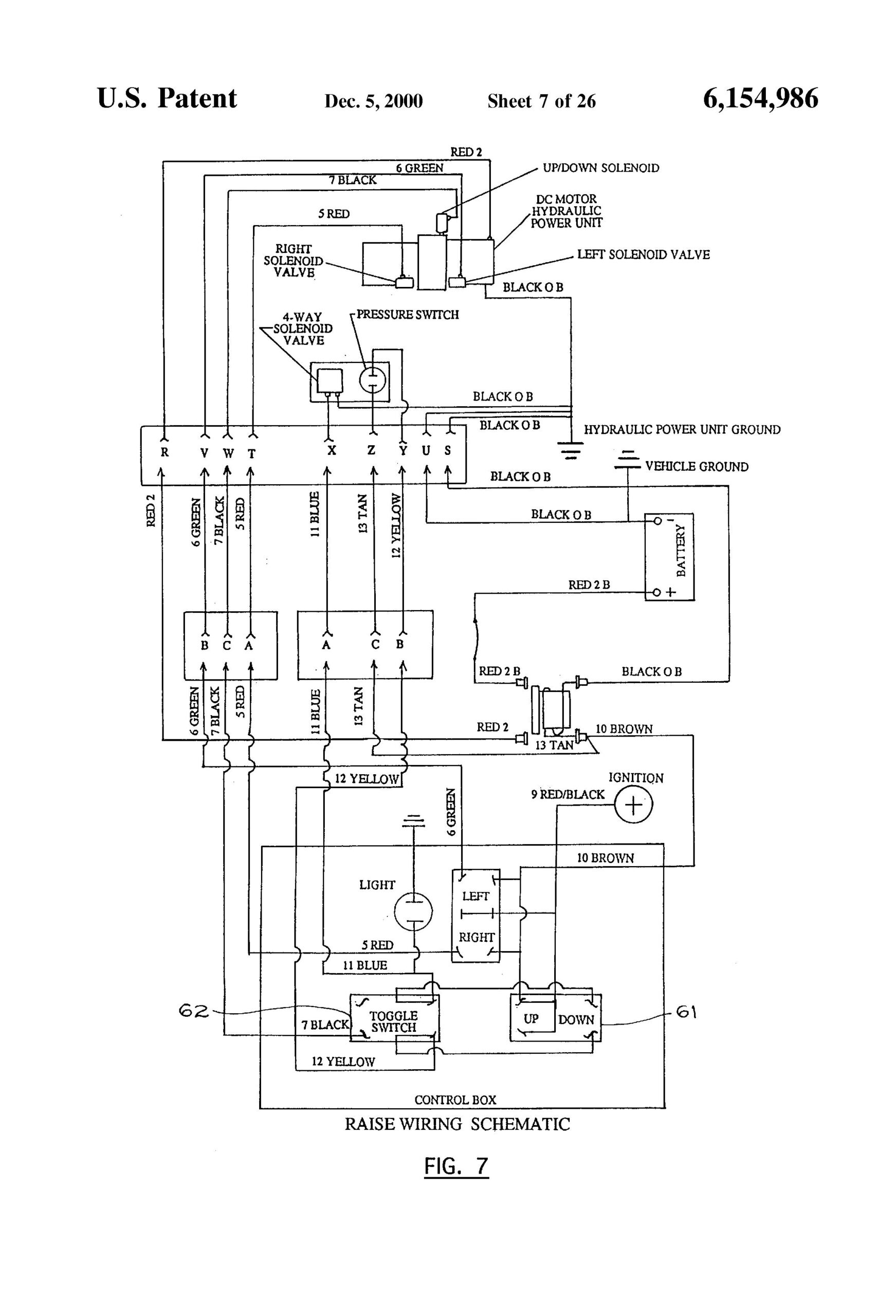
Western Plow Controller Wiring Diagram In 2024 Diagram Electrical Wiring Diagram Snow Plow
The image title is Western Plow Controller Wiring Diagram In 2024 Diagram Electrical Wiring Diagram Snow Plow, features dimensions of width 1743 px and height 2560 px, with a file size of 2320 x 3408 px. This image image/jpeg type visual are source from www.pinterest.com.
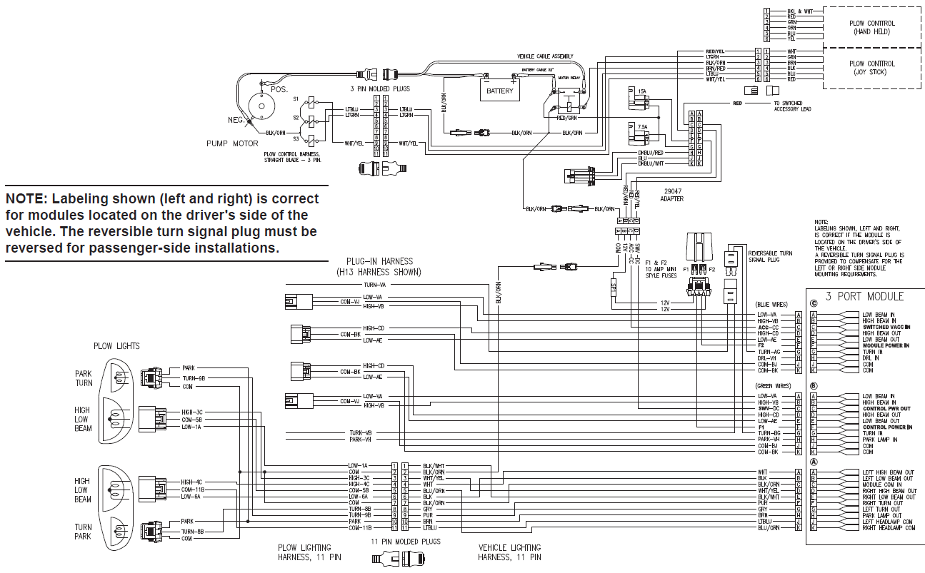
Fisher 3 Port 3 Plug Wiring Kit Isolation Module Truck Side Minute Mount Homesteader
The image title is Fisher 3 Port 3 Plug Wiring Kit Isolation Module Truck Side Minute Mount Homesteader, features dimensions of width 1295 px and height 803 px, with a file size of 1295 x 803. This image image/png type visual are source from www.storksplows.com.
SHOP SNOWPLOW PARTS GENUINE FISHER SNOWPLOWS REPLACEMENT PARTS MINUTE MOUNT 2 PARTS MINUTE MOUNT 2 FLEET FLEX PLOW PARTS 8 1 2 9 1 2 EXTREME V SNOW
The image title is SHOP SNOWPLOW PARTS GENUINE FISHER SNOWPLOWS REPLACEMENT PARTS MINUTE MOUNT 2 PARTS MINUTE MOUNT 2 FLEET FLEX PLOW PARTS 8 1 2 9 1 2 EXTREME V SNOW, features dimensions of width 1108 px and height 808 px, with a file size of 1108 x 808. This image image/png type visual are source from www.fishersnowplowparts.com.
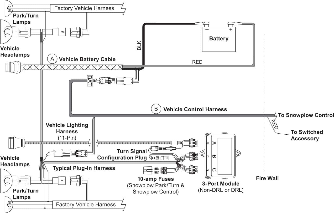
Fisher XV2 VSH XV2 Vehicle Side Harness 3 Port 2 Plug Shop ITEParts
The image title is Fisher XV2 VSH XV2 Vehicle Side Harness 3 Port 2 Plug Shop ITEParts, features dimensions of width 1400 px and height 894 px, with a file size of 1400 x 894. This image image/jpeg type visual are source from iteparts.com
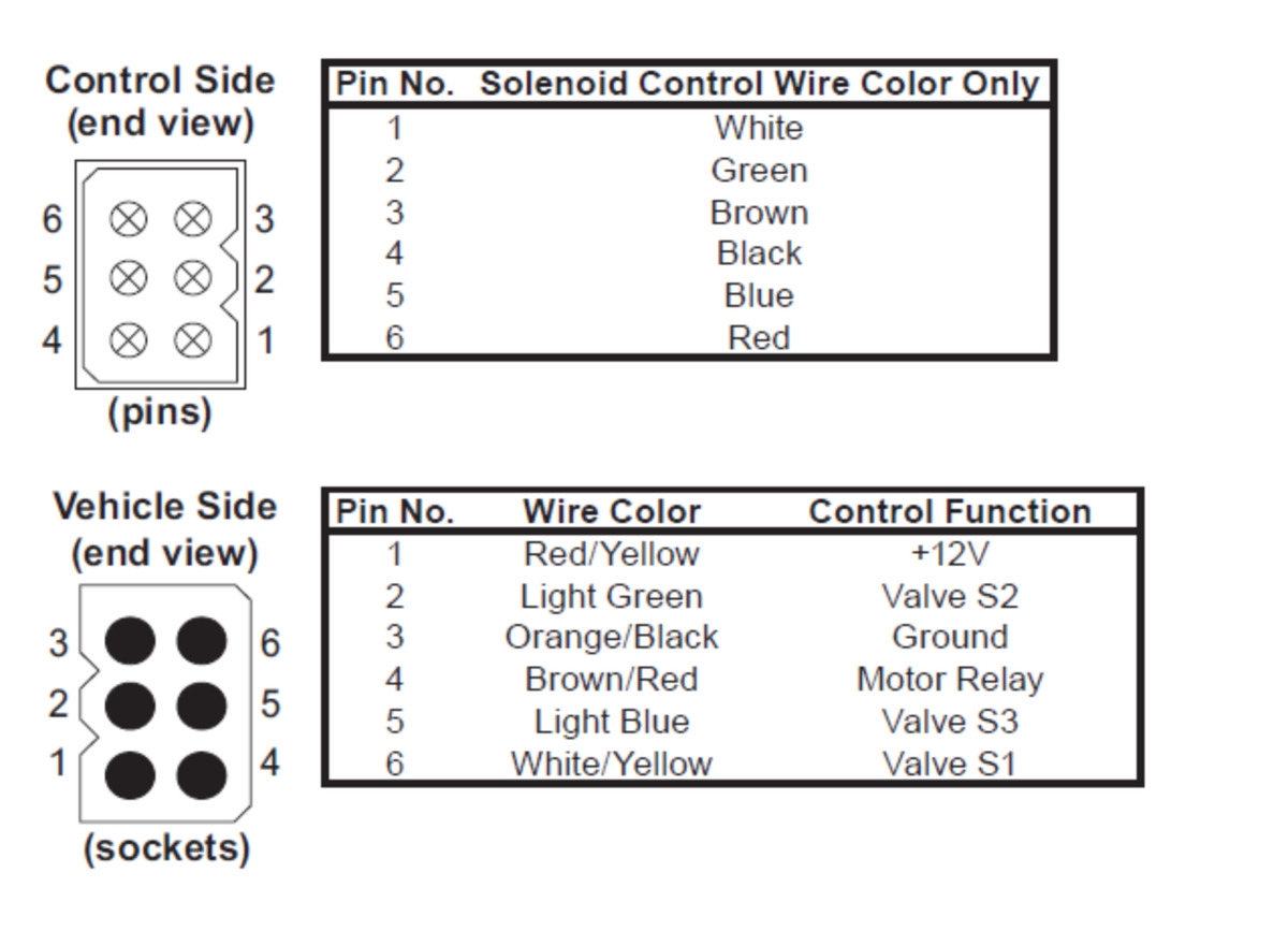
FISHER 6 PIN SNOW PLOW EXTRA LONG 30 TRUCK SIDE REPAIR CORD W SEALED PLUG EBay
The image title is FISHER 6 PIN SNOW PLOW EXTRA LONG 30 TRUCK SIDE REPAIR CORD W SEALED PLUG EBay, features dimensions of width 1200 px and height 867 px, with a file size of 1200 x 867. This image image/jpeg type visual are source from www.ebay.com.
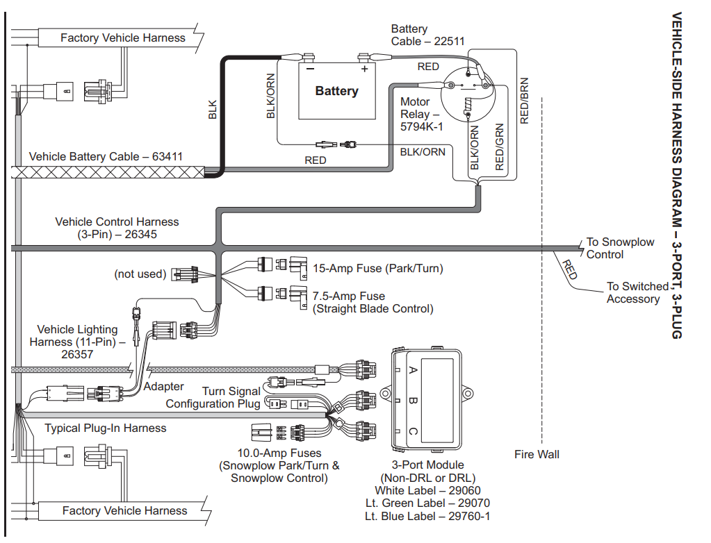
SHOP SNOWPLOW PARTS GENUINE FISHER SNOWPLOWS REPLACEMENT PARTS MINUTE MOUNT 2 PARTS MINUTE MOUNT 2 THREE PLUG PLOWS STRAIGHT PLOWS TRUCK SIDE COMMON WIRING ASH SUPPLY COMPANY LLC
The image title is SHOP SNOWPLOW PARTS GENUINE FISHER SNOWPLOWS REPLACEMENT PARTS MINUTE MOUNT 2 PARTS MINUTE MOUNT 2 THREE PLUG PLOWS STRAIGHT PLOWS TRUCK SIDE COMMON WIRING ASH SUPPLY COMPANY LLC, features dimensions of width 1023 px and height 782 px, with a file size of 1023 x 782. This image image/png type visual are source from www.fishersnowplowparts.com.
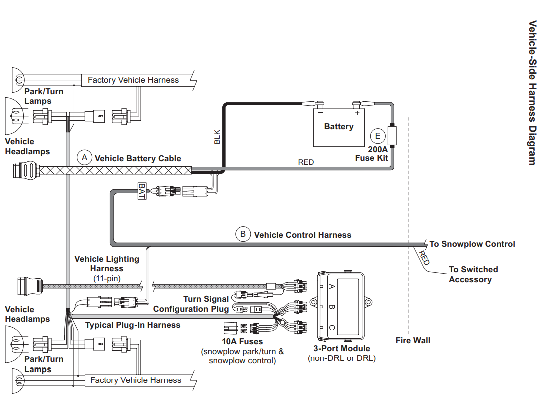
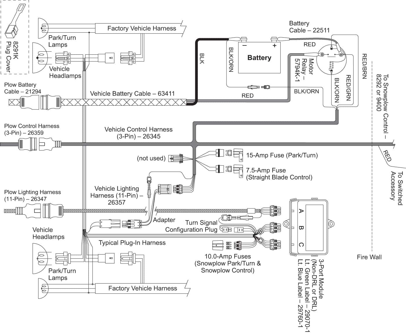
Fisher H VSHD Homesteader Vehicle Side Harness Diagram 3 Port 3 Plug Shop ITEParts
The image title is Fisher H VSHD Homesteader Vehicle Side Harness Diagram 3 Port 3 Plug Shop ITEParts, features dimensions of width 1400 px and height 1150 px, with a file size of 1400 x 1150.
The images on this page, sourced from Google for educational purposes, may be copyrighted. If you own an image and wish its removal or have copyright concerns, please contact us. We aim to promptly address these issues in compliance with our copyright policy and DMCA standards. Your cooperation is appreciated.
Related Keywords to Fisher Plow Controller Wiring Diagram:
fisher plow 4 pin controller wiring diagram,fisher plow 6 pin controller wiring diagram,fisher plow controller wiring diagram,fisher v plow controller wiring diagram,western snow plow controller wiring diagram
