Table of Contents
The Significance of Electric Pto Clutch Wiring Diagram
When it comes to maintaining and troubleshooting your electric PTO clutch, having a comprehensive wiring diagram at your disposal can make all the difference. A well-drawn diagram serves as a roadmap, guiding you through the intricate connections and electrical components of your PTO clutch system. Understanding the wiring layout not only simplifies repairs and installations but also enhances safety by ensuring accurate connections. Let’s delve into the valuable insights that an electric PTO clutch wiring diagram can offer.
Understanding the Components
The first step in deciphering an electric PTO clutch wiring diagram is to familiarize yourself with the various components involved. From the power source to the clutch itself, each element plays a crucial role in the system’s operation. By identifying these components on the diagram, you gain a clearer understanding of how they interact and contribute to the overall functionality of the PTO clutch.
Key Components Include:
- Power Source
- Switches and Controls
- Wiring Harness
- PTO Clutch
- Ground Connections
Interpreting the Connections
One of the primary benefits of a wiring diagram is its ability to illustrate the intricate network of connections within the PTO clutch system. By following the lines and symbols on the diagram, you can trace the flow of electricity from the power source to the clutch, pinpointing any potential issues or malfunctions along the way. This visual representation simplifies troubleshooting and enables you to make informed decisions when repairing or upgrading your PTO clutch.
Common Symbols Found in Wiring Diagrams:
- Wires
- Connections
- Switches
- Grounding Points
- Diodes
Practical Applications
Beyond troubleshooting and repairs, an electric PTO clutch wiring diagram can also be a valuable resource for installation and maintenance tasks. Whether you’re upgrading your PTO clutch or performing routine inspections, referring to the wiring diagram ensures that you adhere to the correct wiring configuration and avoid potential hazards. This proactive approach not only saves time but also promotes the longevity and efficiency of your PTO clutch system.
Benefits of Using a Wiring Diagram for:
- Installation
- Maintenance
- Upgrades
- Inspections
Conclusion
In conclusion, the value of an electric PTO clutch wiring diagram cannot be overstated. By providing a visual representation of the system’s components and connections, the diagram empowers you to navigate the complexities of your PTO clutch with confidence and precision. Whether you’re a seasoned technician or a DIY enthusiast, embracing the insights offered by a wiring diagram can elevate your understanding and proficiency in managing your electric PTO clutch.
Related to Electric Pto Clutch Wiring Diagram
- Electric Guitar Wiring Diagram
- Electric Heat Strip Wiring Diagram
- Electric Heater Wiring Diagram
- Electric Hot Water Heater Wiring Diagram
- Electric Motor Wiring Diagram
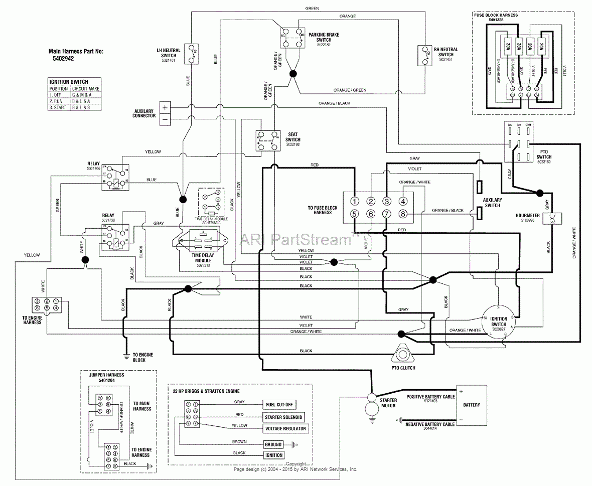
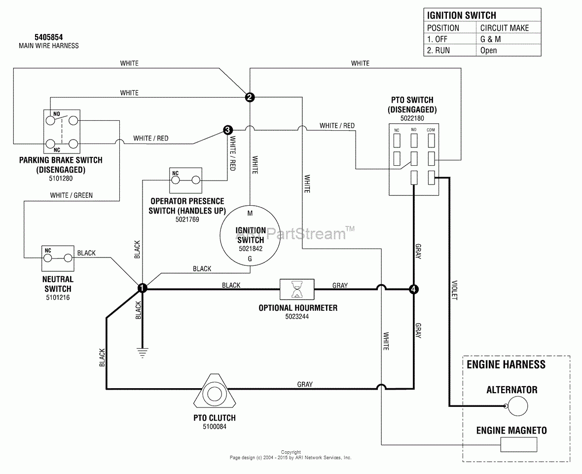
Snapper Pro 5900971 S200XBV32 32HP Briggs Stratton Zero Turn Rider Parts Diagram For Electrical Schematic PTO Clutch Circuit Briggs Stratton Model
The image title is Snapper Pro 5900971 S200XBV32 32HP Briggs Stratton Zero Turn Rider Parts Diagram For Electrical Schematic PTO Clutch Circuit Briggs Stratton Model, features dimensions of width 1180 px and height 969 px, with a file size of 1180 x 969 px. This image image/gif type visual are source from www.jackssmallengines.com.
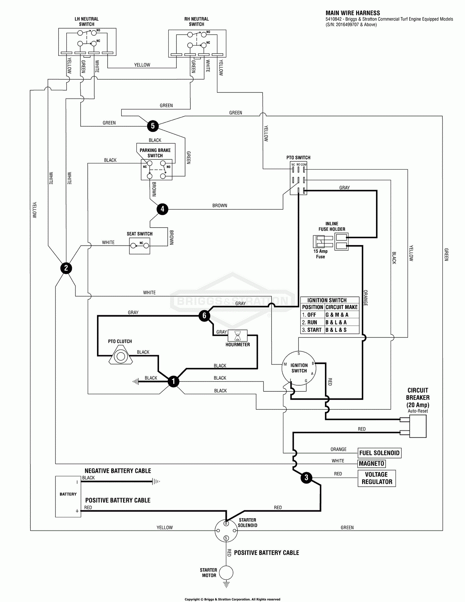
Snapper Pro 5900959 S50XTBS2748 48 Mid Mount Zero Turn Rider Parts Diagram For Electrical Schematic PTO Clutch Circuit B S S N 2016499707 Above
The image title is Snapper Pro 5900959 S50XTBS2748 48 Mid Mount Zero Turn Rider Parts Diagram For Electrical Schematic PTO Clutch Circuit B S S N 2016499707 Above, features dimensions of width 1500 px and height 1941 px, with a file size of 1500 x 1941 px. This image image/gif type visual are source from www.jackssmallengines.com.
Snapper Pro 5900549 SW30KAV2152 52 Walk Behind Mower Parts Diagram For Electrical Schematic PTO Clutch Circuit Kawasaki S N 2016535682 Above
The image title is Snapper Pro 5900549 SW30KAV2152 52 Walk Behind Mower Parts Diagram For Electrical Schematic PTO Clutch Circuit Kawasaki S N 2016535682 Above, features dimensions of width 1500 px and height 1182 px, with a file size of 1500 x 1182. This image image/gif type visual are source from www.jackssmallengines.com.
Electrical Troubleshooting Ride On Mower PTO Clutch Not Engaging Motor Vehicle Maintenance Repair Stack Exchange
The image title is Electrical Troubleshooting Ride On Mower PTO Clutch Not Engaging Motor Vehicle Maintenance Repair Stack Exchange, features dimensions of width 1800 px and height 1272 px, with a file size of 1800 x 1272. This image image/png type visual are source from mechanics.stackexchange.com.
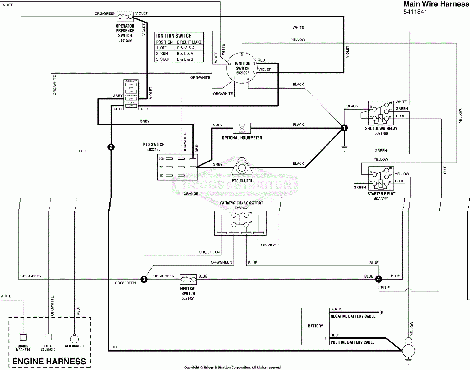
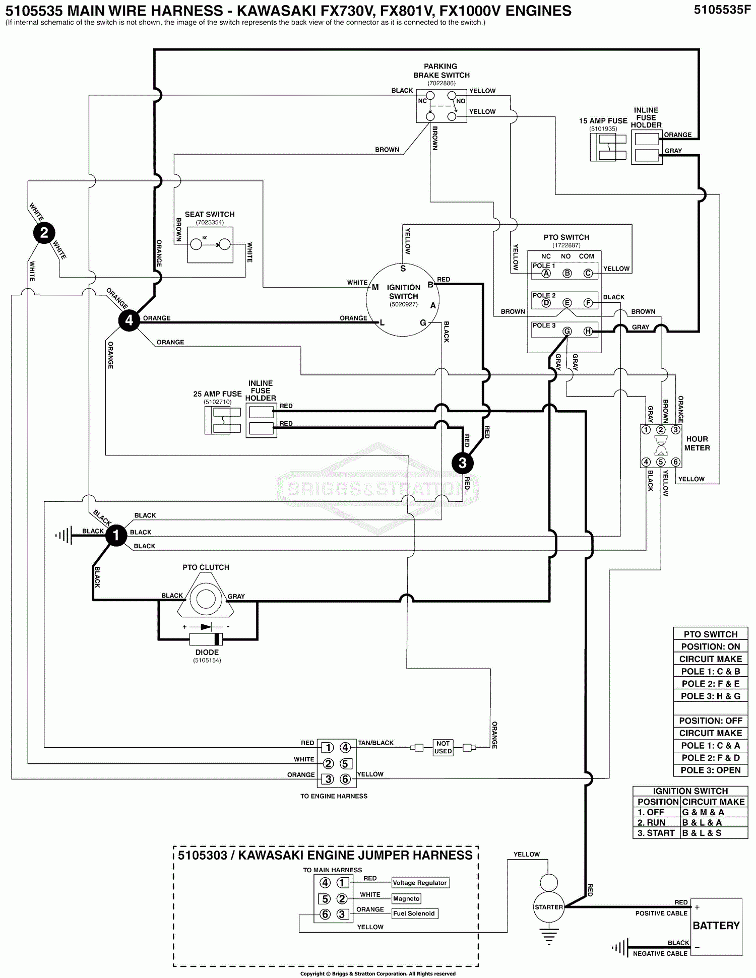
Snapper Pro 5901664 S200XTKAV2661 61 Zero Turn Rider Parts Diagram For Electrical Schematic PTO Clutch Circuit Kawi FX730V FX801V FX1000V S N 2017954956 Above
The image title is Snapper Pro 5901664 S200XTKAV2661 61 Zero Turn Rider Parts Diagram For Electrical Schematic PTO Clutch Circuit Kawi FX730V FX801V FX1000V S N 2017954956 Above, features dimensions of width 1500 px and height 1941 px, with a file size of 1500 x 1941. This image image/gif type visual are source from www.jackssmallengines.com
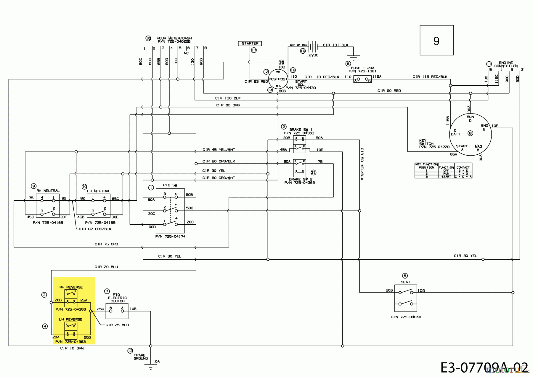
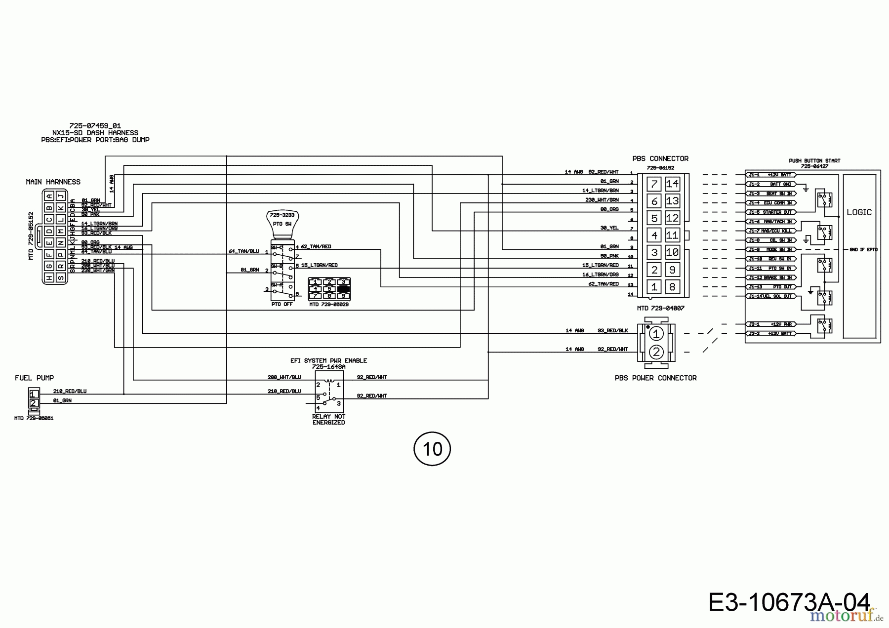
Cub Cadet Lawn Tractors XT2 PS117I 13CZA1CN603 2019 Wiring Diagram Electric Clutch Spareparts
The image title is Cub Cadet Lawn Tractors XT2 PS117I 13CZA1CN603 2019 Wiring Diagram Electric Clutch Spareparts, features dimensions of width 1800 px and height 1272 px, with a file size of 1800 x 1272. This image image/jpeg type visual are source from www.motoruf.com.
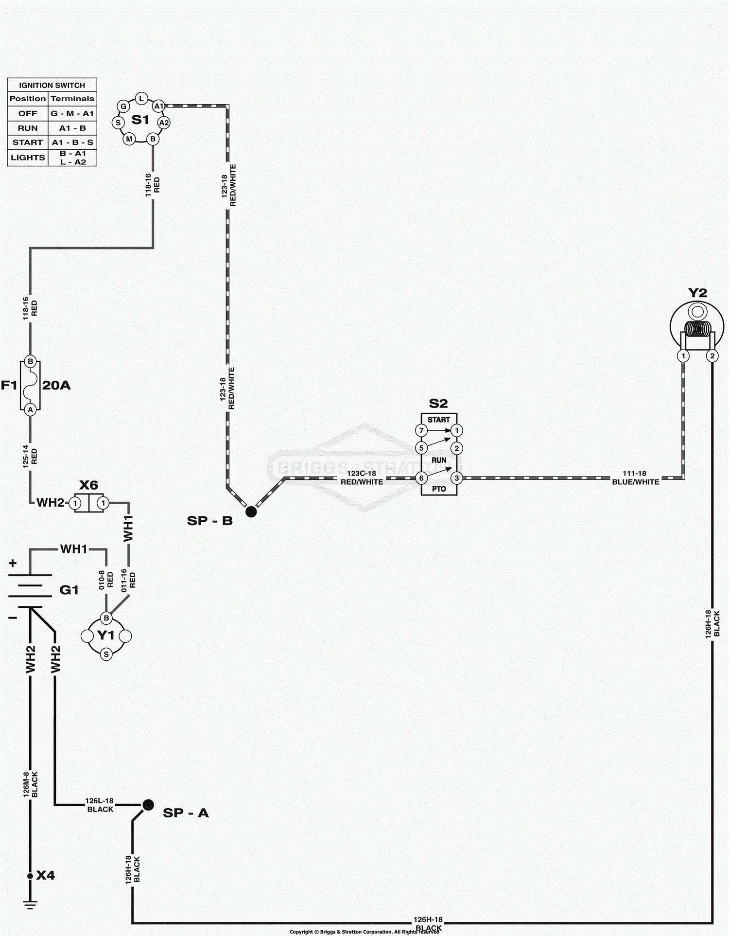
Snapper 2691557 00 SPX2346 46 23 HP SPX Lawn Tractor 150 Series Parts Diagram For Electrical Schematic PTO Clutch
The image title is Snapper 2691557 00 SPX2346 46 23 HP SPX Lawn Tractor 150 Series Parts Diagram For Electrical Schematic PTO Clutch, features dimensions of width 1500 px and height 1925 px, with a file size of 1500 x 1925. This image image/gif type visual are source from www.jackssmallengines.com.
Snapper Pro 5900964 SW30KAV1848 48 Walk Behind Mower Parts Diagram For Electrical Schematic PTO Clutch Circuit Manual Start Kawasaki
The image title is Snapper Pro 5900964 SW30KAV1848 48 Walk Behind Mower Parts Diagram For Electrical Schematic PTO Clutch Circuit Manual Start Kawasaki, features dimensions of width 1180 px and height 961 px, with a file size of 1180 x 961.
The images on this page, sourced from Google for educational purposes, may be copyrighted. If you own an image and wish its removal or have copyright concerns, please contact us. We aim to promptly address these issues in compliance with our copyright policy and DMCA standards. Your cooperation is appreciated.
Related Keywords to Electric Pto Clutch Wiring Diagram:
electric pto clutch wiring diagram,installing electric pto clutch,john deere electric pto clutch wiring diagram
