Table of Contents
Data Link Connector Wiring Diagram: Unraveling the Connection
In the world of automotive diagnostics, understanding the intricate web of wires and connections that make up a vehicle’s Data Link Connector (DLC) wiring diagram is paramount. This essential tool serves as the gateway to accessing crucial diagnostic information, enabling mechanics and technicians to pinpoint issues efficiently and effectively. Whether you’re a seasoned professional or an aspiring enthusiast, delving into the realm of DLC wiring diagrams can unlock a wealth of insights and pave the way for smoother troubleshooting processes.
The Significance of Data Link Connector Wiring Diagram
The Data Link Connector (DLC) is a standardized 16-pin connector found in most vehicles, providing a direct interface for diagnostic tools to communicate with the onboard computer systems. Within this connector lies a network of wires that facilitate the exchange of data between the vehicle’s various electronic components and the diagnostic equipment. By deciphering the DLC wiring diagram, technicians can interpret these intricate connections and harness the power of data-driven diagnostics.
Exploring the Components of a Data Link Connector Wiring Diagram
A typical DLC wiring diagram comprises a series of pins, each serving a specific function in the communication process. From power and ground connections to data transmission lines, every pin plays a crucial role in ensuring seamless communication between the vehicle and diagnostic tools. Understanding the purpose of each pin is essential for troubleshooting issues and interpreting diagnostic codes accurately.
Interpreting Data Link Connector Wiring Diagrams: A Step-by-Step Guide
- Identify the DLC pinout: Begin by locating the DLC connector in your vehicle and familiarizing yourself with the pin configuration. This will serve as the foundation for interpreting the wiring diagram.
- Refer to the manufacturer’s documentation: Consult the vehicle’s service manual or technical guides to access detailed information on the DLC wiring diagram specific to your make and model.
- Trace the wiring connections: Follow the path of each wire from the DLC pins to the corresponding components within the vehicle’s electronic system. This will help you understand how data is transmitted and received through the connector.
- Utilize diagnostic tools: Use OBD scanners and diagnostic software to interface with the DLC and retrieve valuable data regarding the vehicle’s performance and potential issues.
The Practical Applications of Data Link Connector Wiring Diagrams
From diagnosing engine malfunctions to troubleshooting electrical issues, the insights gleaned from DLC wiring diagrams can streamline the repair process and enhance overall efficiency. By leveraging this valuable resource, technicians can expedite diagnostic procedures, identify root causes of problems, and implement targeted solutions with precision.
Related to Data Link Connector Wiring Diagram
- Ct Cabinet Wiring Diagram
- Cub Cadet Ignition Switch Wiring Diagram
- Cub Cadet Starter Solenoid Wiring Diagram
- Cub Cadet Wiring Diagram
- Daisy Chain Wiring Diagram
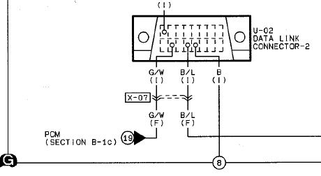
Engine
The image title is Engine, features dimensions of width 460 px and height 252 px, with a file size of 460 x 252 px. This image image/jpeg type visual are source from mstewart.net.
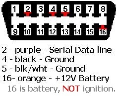
Engine
The image title is Engine, features dimensions of width 236 px and height 195 px, with a file size of 236 x 195 px. This image image/jpeg type visual are source from mstewart.net.
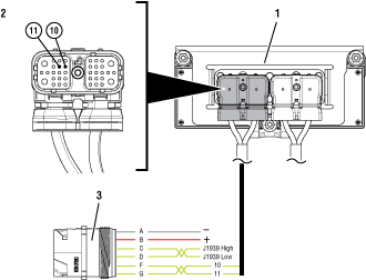
J1587 Data Link TRTS0940
The image title is J1587 Data Link TRTS0940, features dimensions of width 330 px and height 252 px, with a file size of 330 x 252. This image image/png type visual are source from productinfo.serviceranger4.com.
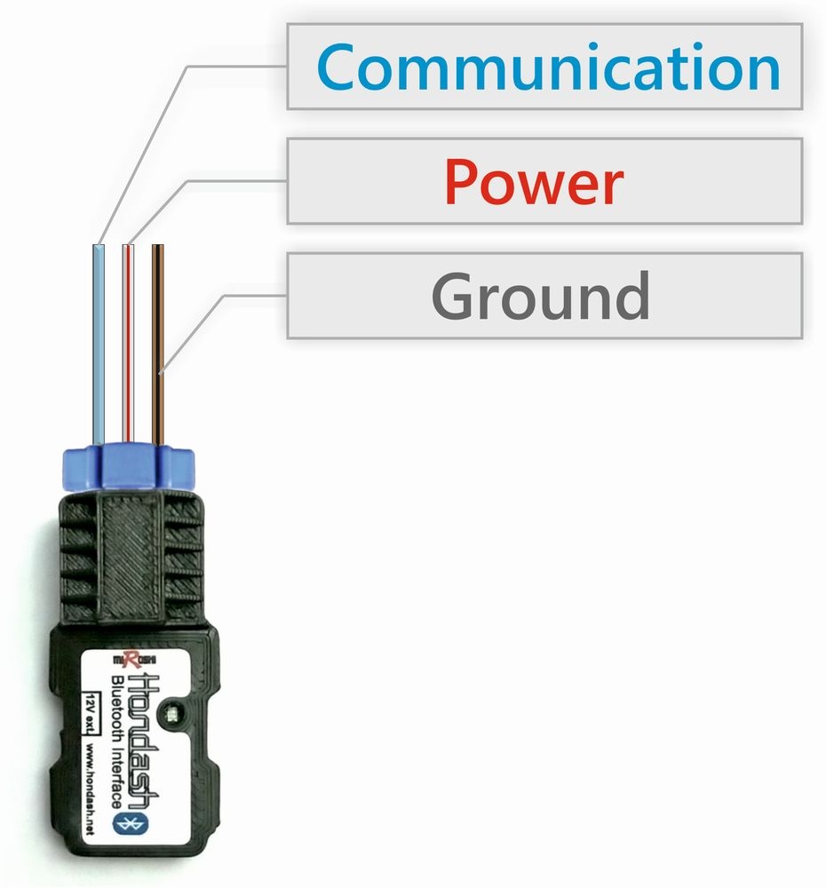
Hondash Wiring And Power Management
The image title is Hondash Wiring And Power Management, features dimensions of width 930 px and height 1000 px, with a file size of 930 x 1000. This image image/jpeg type visual are source from www.hondash.net.
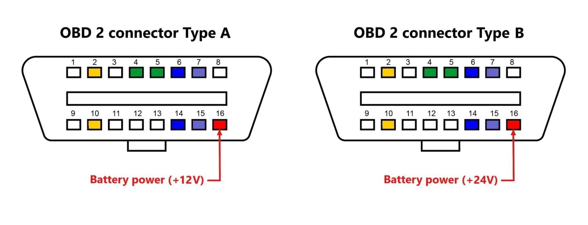
OBD2 Pinout Explained Major Car Brands Pinouts
The image title is OBD2 Pinout Explained Major Car Brands Pinouts, features dimensions of width 1999 px and height 767 px, with a file size of 1999 x 767. This image image/jpeg type visual are source from www.flexihub.com
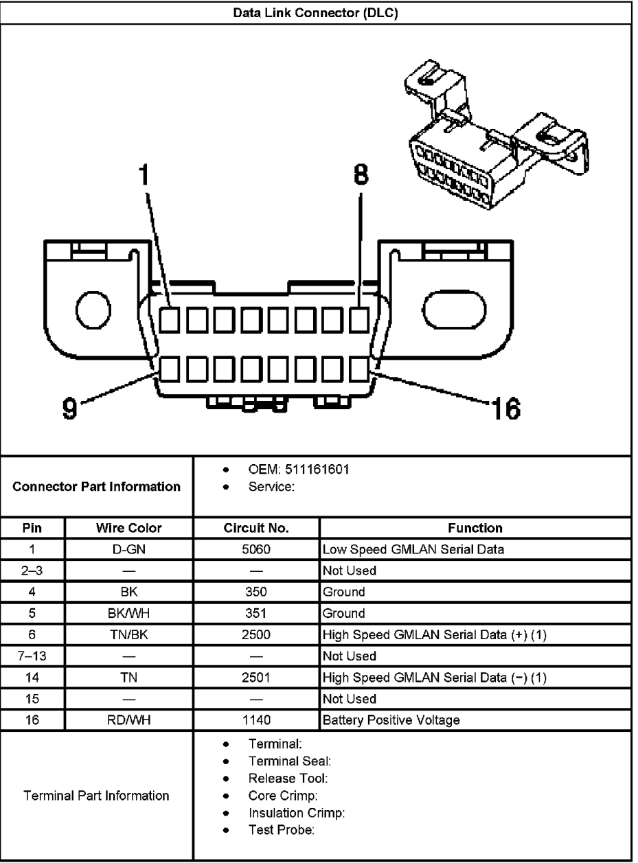
Diagram My OBD 2 Port Is Completely Shredded Need Help With Wiring Motor Vehicle Maintenance Repair Stack Exchange
The image title is Diagram My OBD 2 Port Is Completely Shredded Need Help With Wiring Motor Vehicle Maintenance Repair Stack Exchange, features dimensions of width 929 px and height 1257 px, with a file size of 929 x 1257. This image image/png type visual are source from mechanics.stackexchange.com.
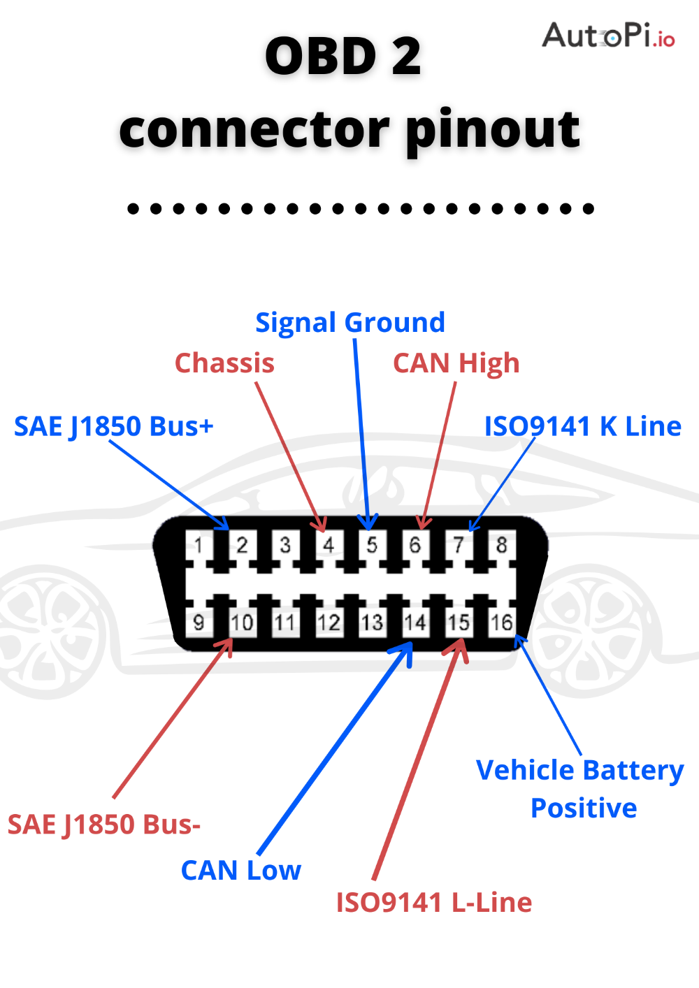
OBD 2 Connector Pinouts Obd On Board Diagnostics Car Diagnostic Tool
The image title is OBD 2 Connector Pinouts Obd On Board Diagnostics Car Diagnostic Tool, features dimensions of width 1000 px and height 1414 px, with a file size of 1000 x 1414. This image image/png type visual are source from www.pinterest.com.
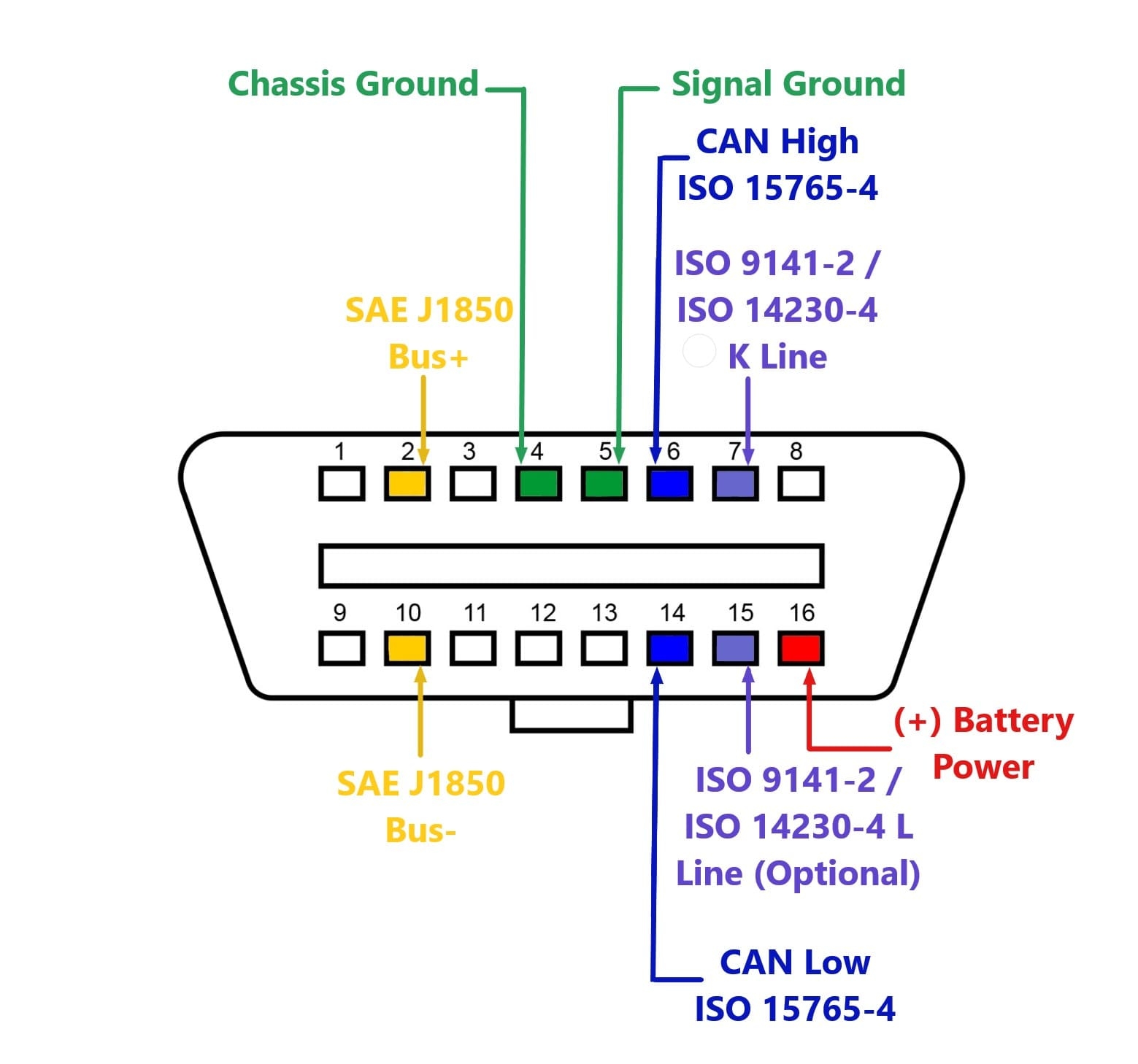
OBD2 Pinout Explained Major Car Brands Pinouts
The image title is OBD2 Pinout Explained Major Car Brands Pinouts, features dimensions of width 1559 px and height 1458 px, with a file size of 1559 x 1458.
The images on this page, sourced from Google for educational purposes, may be copyrighted. If you own an image and wish its removal or have copyright concerns, please contact us. We aim to promptly address these issues in compliance with our copyright policy and DMCA standards. Your cooperation is appreciated.
Related Keywords to Data Link Connector Wiring Diagram:
data link connector wiring diagram,j1939 data link connector wiring diagram,what is a data link cable,what is a data link connector
