Table of Contents
Exploring the Value of Autometer Tach Wiring Diagram
In the realm of automotive enthusiasts and mechanics, precision and accuracy are paramount. The Autometer Tach Wiring Diagram serves as a crucial tool in ensuring the proper installation and functioning of tachometers, vital for monitoring engine RPM and performance. Understanding the intricacies of wiring diagrams not only streamlines the installation process but also enhances the overall efficiency and accuracy of your tachometer. Let’s delve into the world of Autometer Tach Wiring Diagram to unlock its full potential and optimize your automotive experience.
The Basics of Autometer Tach Wiring Diagram
Before delving into the specifics of Autometer Tach Wiring Diagram, it’s essential to grasp the fundamental principles behind tachometer installation. A tachometer, commonly referred to as a ‘tach,’ measures the revolutions per minute (RPM) of an engine’s crankshaft. This information is crucial for monitoring engine performance, detecting potential issues, and optimizing driving efficiency. The Autometer Tach Wiring Diagram provides a detailed schematic that guides users through the wiring process, ensuring seamless integration and accurate readings.
Key Components of Autometer Tach Wiring Diagram
The Autometer Tach Wiring Diagram typically includes essential components such as power source connections, signal input, ground connections, and lighting features. Each component plays a vital role in the proper functioning of the tachometer, and the wiring diagram illustrates how these elements interconnect to create a cohesive system. By following the diagram meticulously, users can avoid common pitfalls and errors during installation, guaranteeing optimal performance and longevity of the tachometer.
Benefits of Utilizing Autometer Tach Wiring Diagram
The value of the Autometer Tach Wiring Diagram extends beyond mere installation guidance. By leveraging the diagram effectively, users can benefit from enhanced accuracy, reliability, and customization options for their tachometer setup. Understanding the wiring layout facilitates troubleshooting and maintenance, empowering users to address issues promptly and efficiently. Additionally, the diagram serves as a valuable reference tool for future modifications or upgrades, ensuring seamless integration with existing systems.
Tips for Maximizing the Potential of Autometer Tach Wiring Diagram
- Thoroughly study the wiring diagram before commencing the installation process to familiarize yourself with the connections and components.
- Ensure all connections are secure and properly insulated to prevent electrical malfunctions or short circuits.
- Consult manufacturer guidelines and support resources to clarify any doubts or queries regarding the wiring diagram.
- Regularly inspect and maintain the tachometer wiring to uphold optimal performance and reliability over time.
Conclusion
In conclusion, the Autometer Tach Wiring Diagram serves as a cornerstone for achieving precision and efficiency in tachometer installation. By embracing the guidance provided in the wiring diagram, users can elevate their automotive experience, enhance performance monitoring, and ensure long-term reliability of their tachometer system. Whether you’re a seasoned enthusiast or a novice mechanic, understanding and implementing the Autometer Tach Wiring Diagram can unlock a world of possibilities in the realm of automotive instrumentation.
Related to Autometer Tach Wiring Diagram
- Auto Wiring Diagram
- Auto Wiring Diagram Symbols
- Auto Wiring Diagrams Free
- Automatic 3 Wire Bilge Pump Wiring Diagram
- Automatic Transfer Switch Wiring Diagram
RPM SIGNAL ADAPTER FOR LS ENGINES INCL PLUG PLAY HARNESS
The image title is RPM SIGNAL ADAPTER FOR LS ENGINES INCL PLUG PLAY HARNESS, features dimensions of width 1500 px and height 1500 px, with a file size of 1500 x 1500 px. This image image/jpeg type visual are source from www.autometer.com.
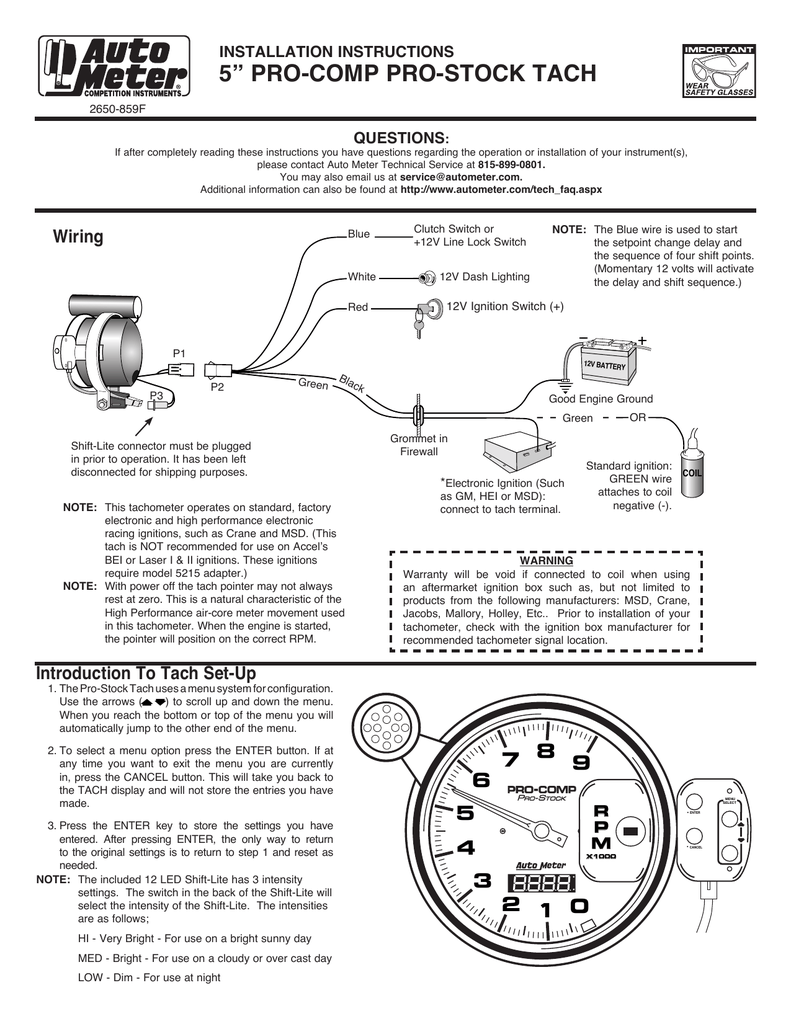
Elite Street Tach Wiring INSTALLATION INSTRUCTIONS Manualzz
The image title is Elite Street Tach Wiring INSTALLATION INSTRUCTIONS Manualzz, features dimensions of width 791 px and height 1024 px, with a file size of 791 x 1024 px. This image image/png type visual are source from manualzz.com.
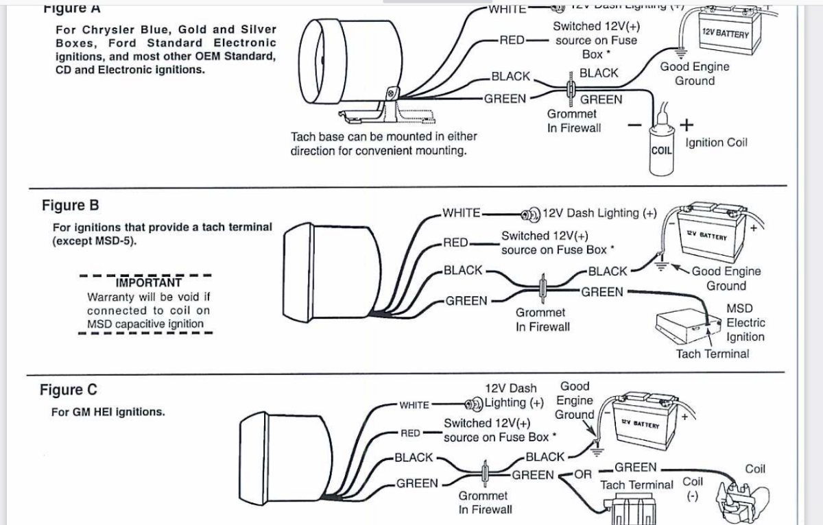
Aftermarket Tach For A KA24DE 510 1600 Ratsun Forums
The image title is Aftermarket Tach For A KA24DE 510 1600 Ratsun Forums, features dimensions of width 1200 px and height 766 px, with a file size of 1200 x 766. This image image/png type visual are source from ratsun.net.
Autometer AU3910 Sport Comp Silver Tachometer 5 With Adjustable Redline Pointer EBay
The image title is Autometer AU3910 Sport Comp Silver Tachometer 5 With Adjustable Redline Pointer EBay, features dimensions of width 1000 px and height 1000 px, with a file size of 1000 x 1000. This image image/jpeg type visual are source from www.ebay.com.
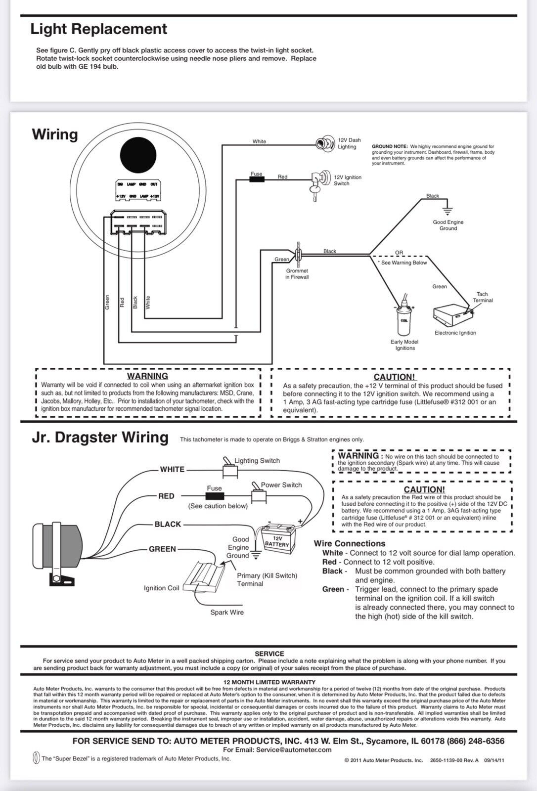
6601 AutoMeter Memory Tachometer Pro Comp 3 3 4 0 10000 Rpm Pedestal Jr Drag Renzi Ceramiche
The image title is 6601 AutoMeter Memory Tachometer Pro Comp 3 3 4 0 10000 Rpm Pedestal Jr Drag Renzi Ceramiche, features dimensions of width 1086 px and height 1600 px, with a file size of 1086 x 1600. This image image/jpeg type visual are source from www.renziceramiche.it
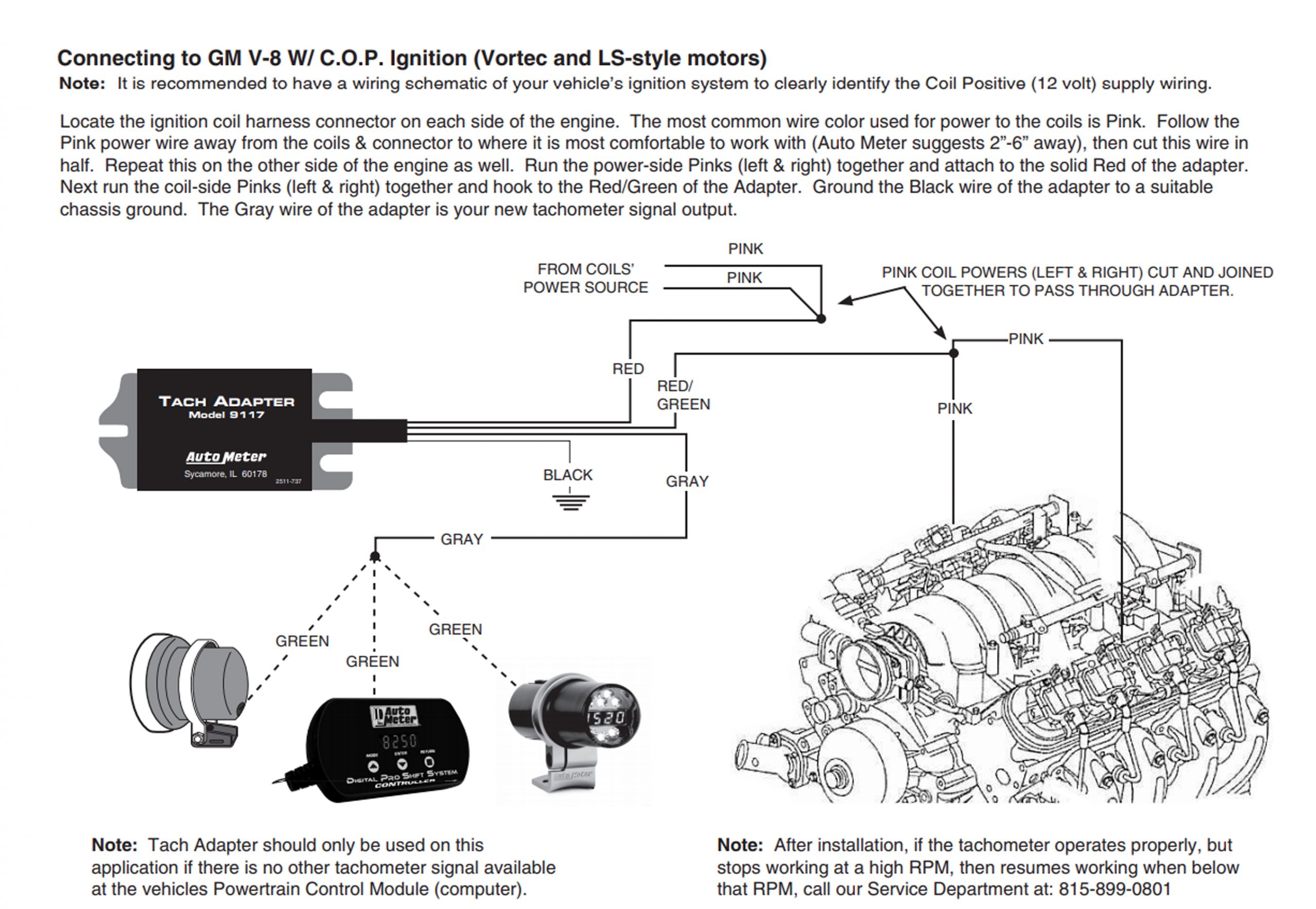
Ask Away With Jeff Smith Getting An Aftermarket Tach To Work In An LS Swapped 1969 Chevy Nova
The image title is Ask Away With Jeff Smith Getting An Aftermarket Tach To Work In An LS Swapped 1969 Chevy Nova, features dimensions of width 2560 px and height 1769 px, with a file size of 2560 x 1769. This image image/jpeg type visual are source from www.onallcylinders.com.
Auto Meter Pro Stock Playback Tachometers Owner Manual Manualzz
The image title is Auto Meter Pro Stock Playback Tachometers Owner Manual Manualzz, features dimensions of width 791 px and height 1024 px, with a file size of 791 x 1024. This image image/png type visual are source from manualzz.com.
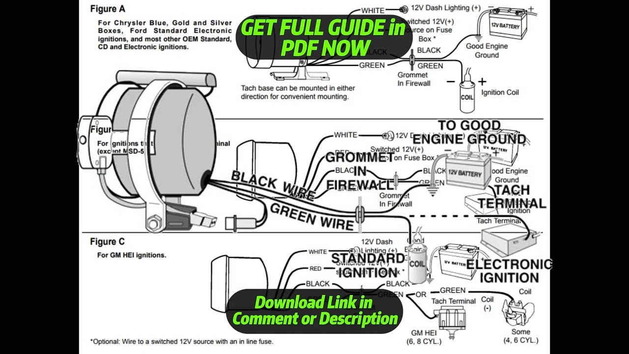
DIAGRAM Autometer Tach Wiring Diagram YouTube
The image title is DIAGRAM Autometer Tach Wiring Diagram YouTube, features dimensions of width 1280 px and height 720 px, with a file size of 1280 x 720.
The images on this page, sourced from Google for educational purposes, may be copyrighted. If you own an image and wish its removal or have copyright concerns, please contact us. We aim to promptly address these issues in compliance with our copyright policy and DMCA standards. Your cooperation is appreciated.
Related Keywords to Autometer Tach Wiring Diagram:
auto meter auto gauge tach wiring diagram,auto meter tachometer wiring diagram,autometer street tach wiring diagram,autometer tach wiring diagram,autometer tach wiring schematic


