Table of Contents
The Ultimate Guide to Air Ride Pressure Switch Wiring Diagram
The Ultimate Guide to Air Ride Pressure Switch Wiring Diagram
When it comes to ensuring the optimal performance of your air ride suspension system, understanding the intricacies of the pressure switch wiring diagram is paramount. This vital component not only regulates the air pressure within the system but also plays a crucial role in maintaining a smooth and comfortable ride. In this comprehensive guide, we delve into the nuances of air ride pressure switch wiring diagrams, shedding light on their importance and providing valuable insights for enthusiasts and professionals alike.
The Basics of Air Ride Pressure Switch Wiring Diagram
At the core of any air ride suspension system lies the pressure switch, a device that monitors and controls the air pressure to ensure optimal performance. The wiring diagram for this component elucidates the connections between various elements such as the compressor, air tank, valves, and sensors. By following this diagram meticulously, you can troubleshoot issues, make adjustments, and enhance the overall functionality of your air ride system.
Key Components in the Wiring Diagram
Understanding the key components outlined in the air ride pressure switch wiring diagram is essential for grasping the system’s functionality. These components include:
Compressor: Responsible for pressurizing the air within the system.
Air Tank: Stores the compressed air for use in the suspension system.
Valves: Control the flow of air to different parts of the system.
Sensors: Monitor the air pressure levels and provide feedback to the pressure switch.
Importance of Proper Wiring
Proper wiring of the air ride pressure switch is crucial for ensuring the system operates smoothly and efficiently. Any errors in the wiring can lead to malfunctions, decreased performance, or even damage to the components. By following the wiring diagram meticulously and using high-quality materials, you can avoid potential issues and enjoy a reliable air ride experience.
Step-by-Step Guide for Wiring the Pressure Switch
Identify the terminals on the pressure switch and their corresponding functions.
Refer to the wiring diagram to determine the correct connections for each terminal.
Securely connect the wires from the compressor, air tank, valves, and sensors to the respective terminals on the pressure switch.
Double-check the connections to ensure they are secure and properly aligned.
Test the system to verify that the pressure switch is functioning correctly and regulating the air pressure effectively.
Conclusion
In conclusion, the air ride pressure switch wiring diagram serves as a crucial blueprint for maintaining and optimizing your suspension system. By understanding the components, following the wiring guidelines, and conducting regular checks, you can ensure the smooth operation of your air ride system for years to come. Whether you are a seasoned enthusiast or a novice in the world of air suspension, this guide equips you with the knowledge and insights needed to navigate the complexities of pressure switch wiring diagrams with confidence.
Related to Air Ride Pressure Switch Wiring Diagram
- Air Conditioning Compressor Wiring Diagram
- Air Conditioning Wiring Diagram
- Air Handler Wiring Diagram
- Air Horn Relay Wiring Diagram
- Air Horn Wiring Diagram
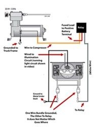
Wiring Diagram For Firestone Level Command II On Board Compressor Kit For Air Bag Suspensions Air Ride Air Bag Diagram
The image title is Wiring Diagram For Firestone Level Command II On Board Compressor Kit For Air Bag Suspensions Air Ride Air Bag Diagram, features dimensions of width 201 px and height 250 px, with a file size of 201 x 250 px. This image image/jpeg type visual are source from www.pinterest.com.
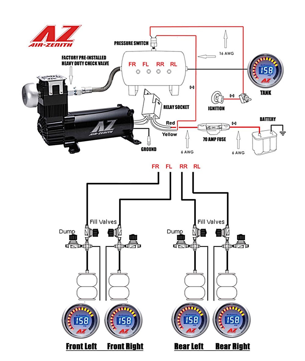
Tech Support Air Zenith
The image title is Tech Support Air Zenith, features dimensions of width 1000 px and height 1182 px, with a file size of 1000 x 1182 px. This image image/jpeg type visual are source from air-zenith.com.
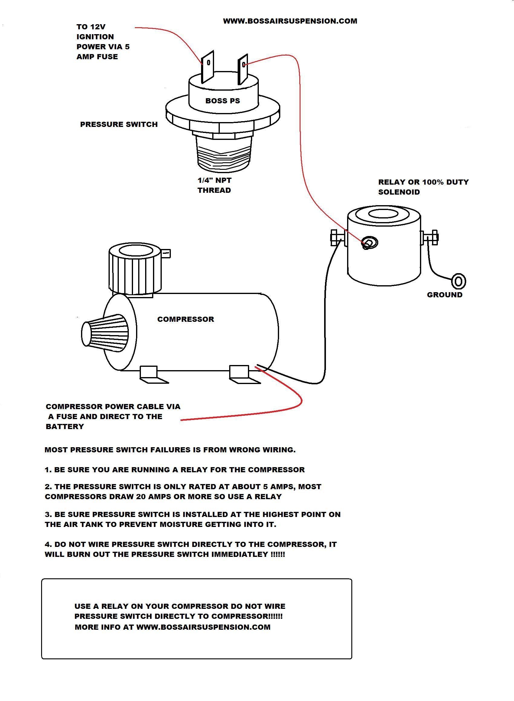
Pressure Switch 70 100psi Boss Air Suspension
The image title is Pressure Switch 70 100psi Boss Air Suspension, features dimensions of width 1700 px and height 2320 px, with a file size of 1700 x 2320. This image image/jpeg type visual are source from bossairsuspension.com.
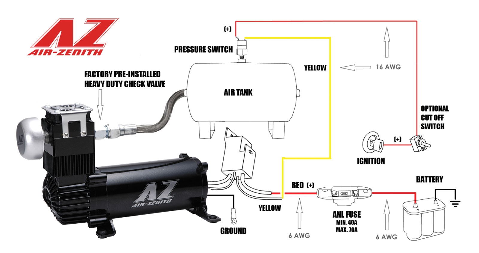
Tech Support Air Zenith
The image title is Tech Support Air Zenith, features dimensions of width 1600 px and height 844 px, with a file size of 1600 x 844. This image image/jpeg type visual are source from air-zenith.com.
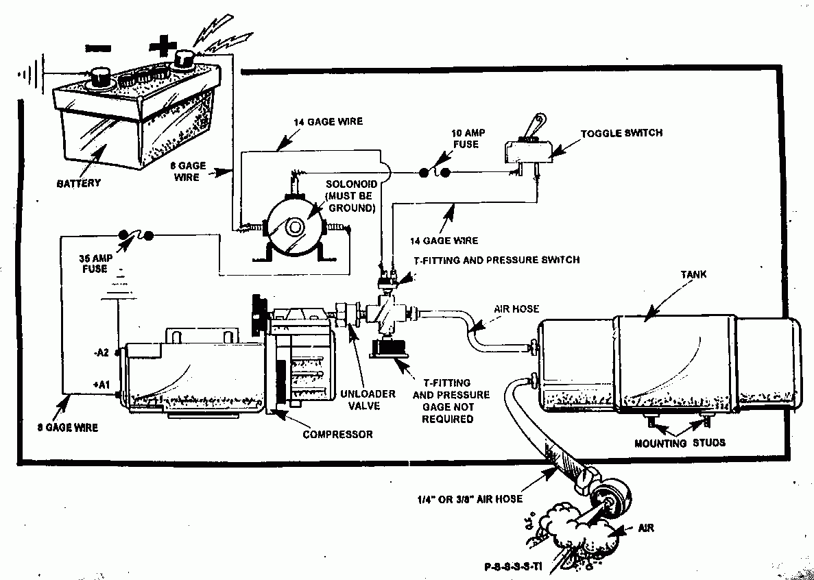
OBA Wiring Diagram XterraNation
The image title is OBA Wiring Diagram XterraNation, features dimensions of width 1187 px and height 846 px, with a file size of 1187 x 846. This image image/gif type visual are source from www.xterranation.org
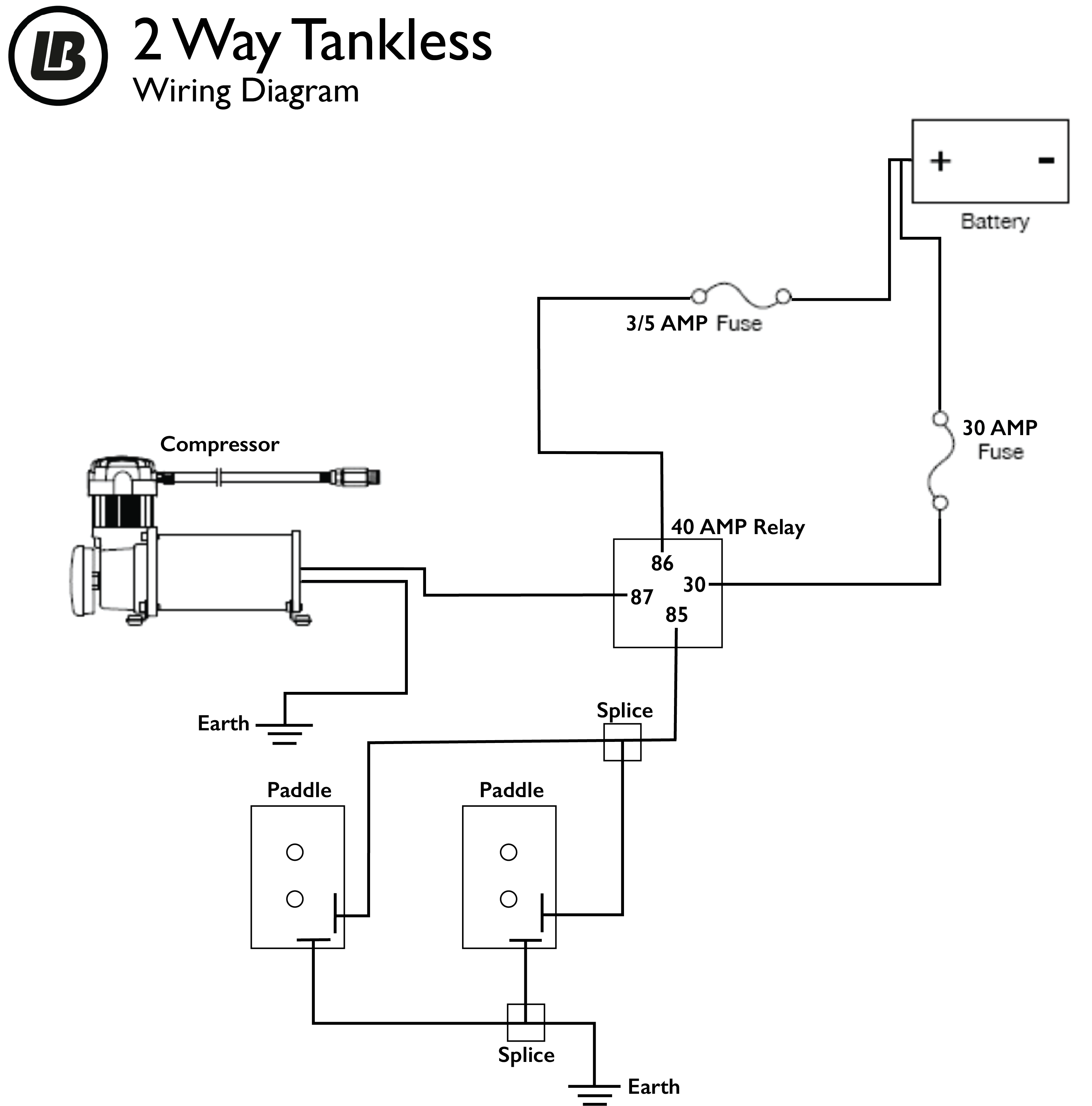
2 Way Tankless Air Management Wiring Pneumatic Diagrams Limebug
The image title is 2 Way Tankless Air Management Wiring Pneumatic Diagrams Limebug, features dimensions of width 3122 px and height 3162 px, with a file size of 3122 x 3162. This image image/png type visual are source from limebug.com.
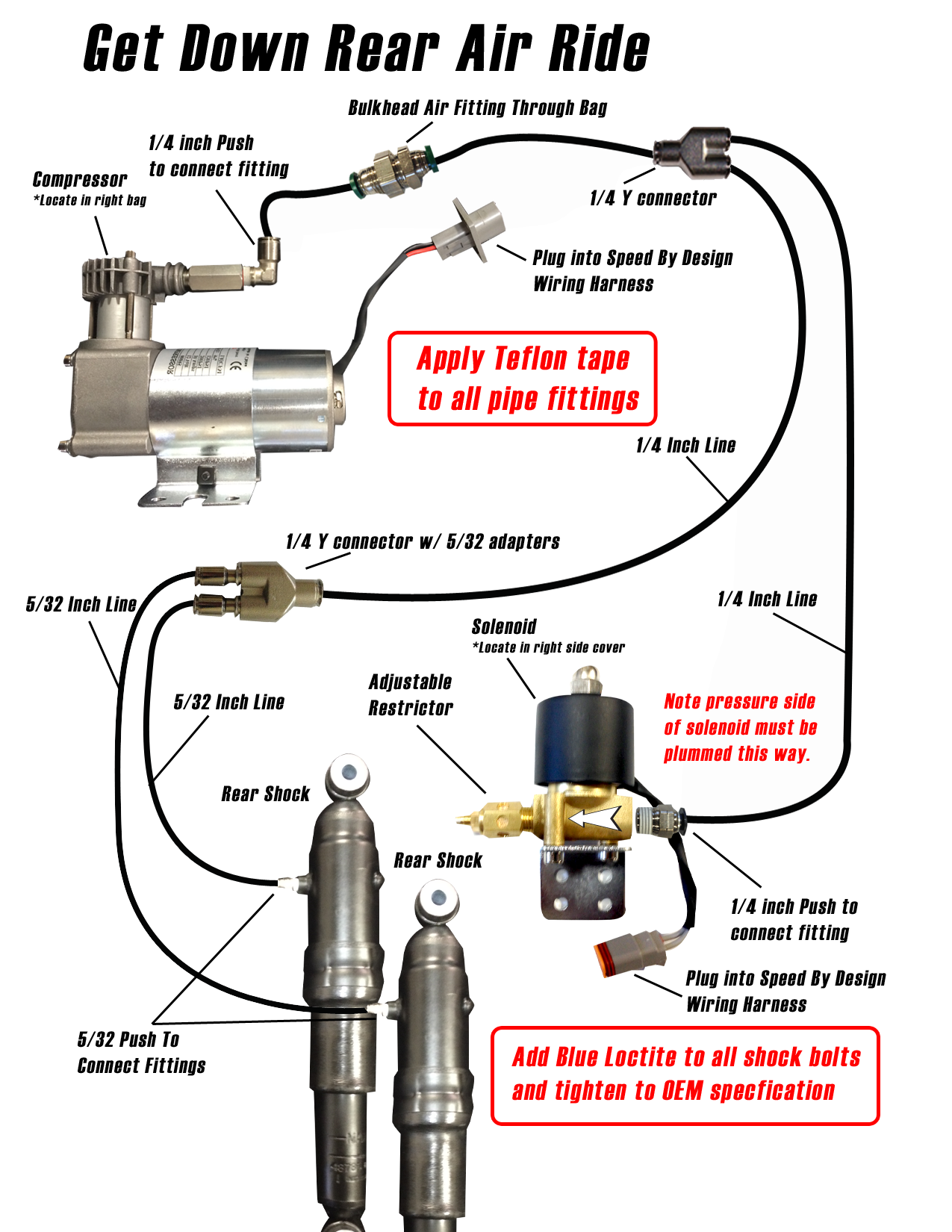
Harley Fast Up Air Ride Rear Kit Diagram Speed By Design
The image title is Harley Fast Up Air Ride Rear Kit Diagram Speed By Design, features dimensions of width 1275 px and height 1650 px, with a file size of 1275 x 1650. This image image/png type visual are source from speedbydesign.net.
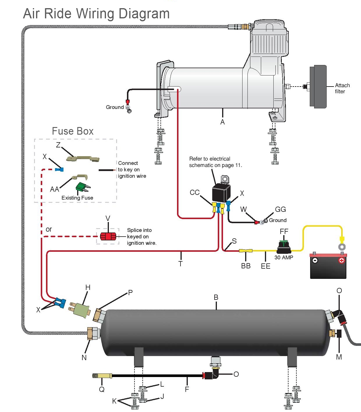
Manual Air Ride Management Kit Wiring Valve Pneumatic Diagrams Limebug
The image title is Manual Air Ride Management Kit Wiring Valve Pneumatic Diagrams Limebug, features dimensions of width 1240 px and height 1414 px, with a file size of 1240 x 1414.
The images on this page, sourced from Google for educational purposes, may be copyrighted. If you own an image and wish its removal or have copyright concerns, please contact us. We aim to promptly address these issues in compliance with our copyright policy and DMCA standards. Your cooperation is appreciated.
Related Keywords to Air Ride Pressure Switch Wiring Diagram:
air ride pressure switch not working,air ride pressure switch wiring diagram,how does an air pressure switch work,how to wire a pressure switch for air ride
