Table of Contents
Exploring the 4 Wire Oxygen Sensor Wiring Diagram
The Value of Understanding the 4 Wire Oxygen Sensor Wiring Diagram
When it comes to optimizing the performance of your vehicle’s engine, having a deep understanding of the 4 wire oxygen sensor wiring diagram is crucial. This diagram serves as a blueprint for connecting the oxygen sensor to the engine’s control unit, ensuring precise measurements of the air-fuel mixture for efficient combustion. By delving into the intricacies of this wiring diagram, you can unlock the full potential of your vehicle’s engine, leading to enhanced performance and fuel efficiency.
Understanding the Basics of a 4 Wire Oxygen Sensor
Before diving into the wiring diagram, it’s essential to grasp the fundamentals of a 4 wire oxygen sensor. This type of sensor plays a vital role in monitoring the oxygen levels in the exhaust gases, providing valuable feedback to the engine control unit. By analyzing this data, the engine can adjust the air-fuel mixture in real-time, optimizing combustion efficiency.
Key Components of a 4 Wire Oxygen Sensor
Sensor Body
Heater Element
Signal Wire
Ground Wire
Importance of the Wiring Diagram
The wiring diagram acts as a roadmap for connecting the oxygen sensor to the engine’s control unit. By following this diagram meticulously, you can ensure that the sensor operates seamlessly, providing accurate readings to the ECU. Any deviations from the specified wiring configuration can lead to faulty readings and potential engine performance issues.
Benefits of Proper Wiring
Optimal Engine Performance
Improved Fuel Efficiency
Enhanced Emission Control
Step-by-Step Guide to Wiring the 4 Wire Oxygen Sensor
Identify the Sensor Wires
Match the Wires to the ECU
Connect the Heater Element
Secure Ground Connection
Common Wiring Mistakes to Avoid
While understanding the wiring diagram is crucial, it’s also essential to steer clear of common wiring mistakes that can compromise sensor performance. Avoiding issues such as incorrect wire connections or poor grounding can help maintain the sensor’s accuracy and reliability.
Common Mistakes to Avoid
Incorrect Wire Matching
Poor Grounding
Excessive Wire Length
Conclusion
In conclusion, delving into the intricacies of the 4 wire oxygen sensor wiring diagram is a valuable endeavor for any vehicle enthusiast. By understanding the role of each wire and component, you can ensure that the sensor operates optimally, leading to improved engine performance and fuel efficiency. Remember to follow the wiring diagram diligently and avoid common mistakes to reap the full benefits of this essential engine component.
Related to 4 Wire Oxygen Sensor Wiring Diagram
- 4 Wire Mobile Home Wiring Diagram
- 4 Wire Motor Wiring Diagram
- 4 Wire O2 Sensor Wiring Diagram
- 4 Wire O2 Sensor Wiring Diagram Honda
- 4 Wire O2 Sensor Wiring Diagram Nissan
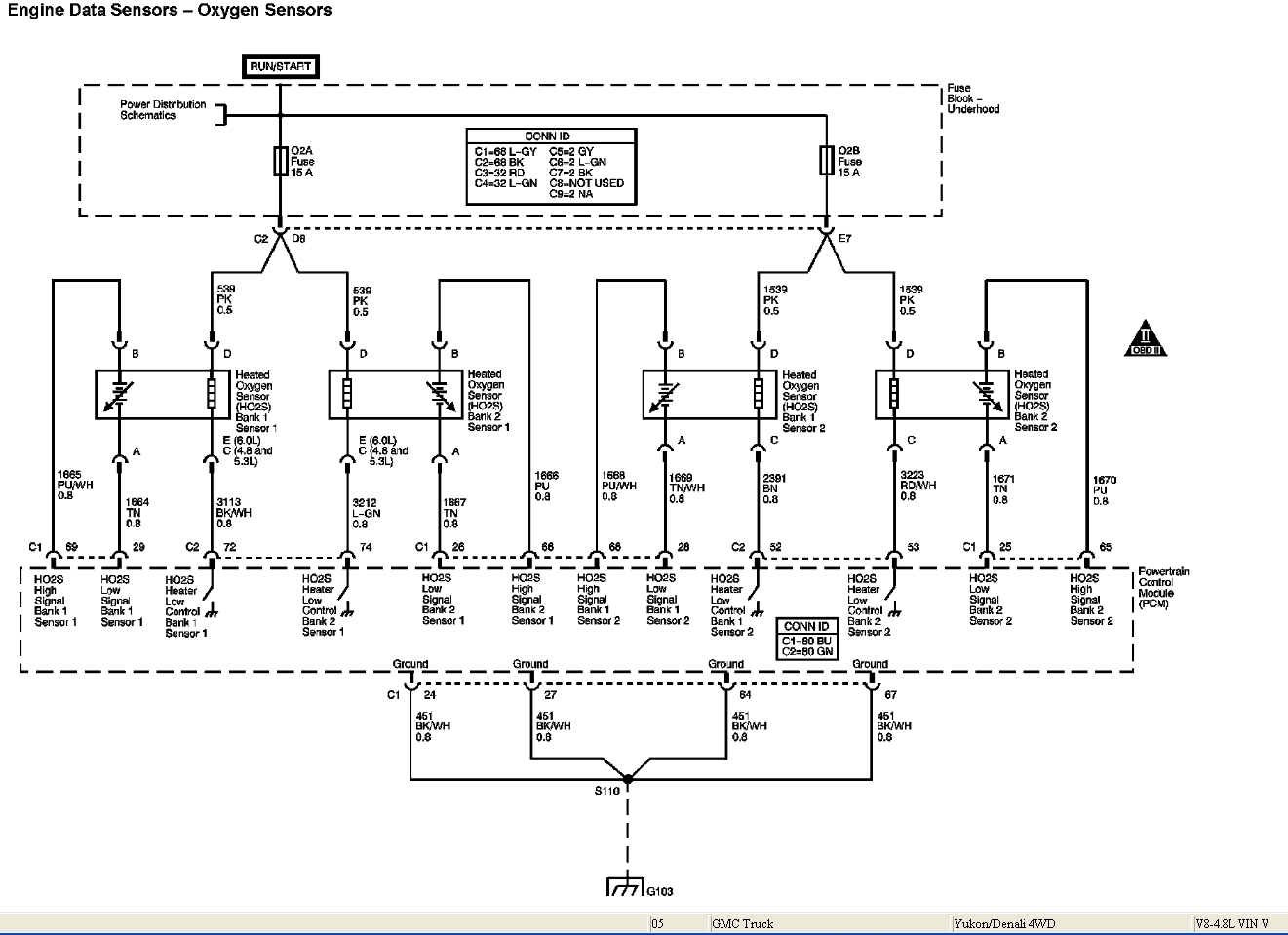
Wiring Trouble Rewiring O2 Sensor Harness After Dogs Ate It Motor Vehicle Maintenance Repair Stack Exchange
The image title is Wiring Trouble Rewiring O2 Sensor Harness After Dogs Ate It Motor Vehicle Maintenance Repair Stack Exchange, features dimensions of width 1321 px and height 959 px, with a file size of 1321 x 959 px. This image image/jpeg type visual are source from mechanics.stackexchange.com.
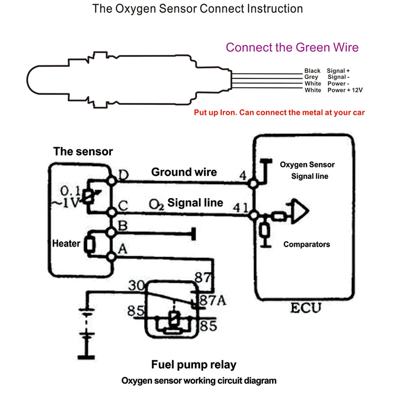
Oxygen Lambda Sensor Universal Oxygen Sensor 4 Cables Narrowband O2 Oxygen Sensor Cars Accessories 0258006028 Exhaust Gas Oxygen Sensor AliExpress
The image title is Oxygen Lambda Sensor Universal Oxygen Sensor 4 Cables Narrowband O2 Oxygen Sensor Cars Accessories 0258006028 Exhaust Gas Oxygen Sensor AliExpress, features dimensions of width 1600 px and height 1600 px, with a file size of 1600 x 1600 px. This image image/jpeg type visual are source from www.aliexpress.com.
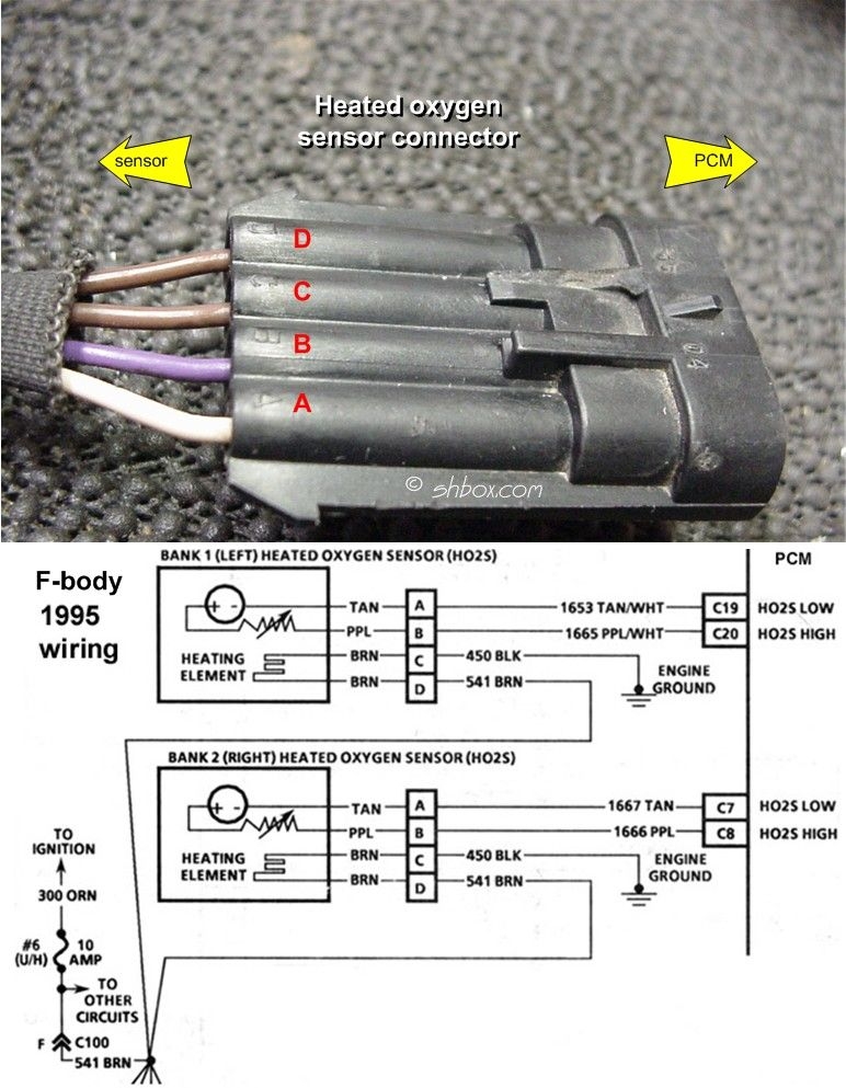
Automotive Mechanic Automotive Technician Car Radiator
The image title is Automotive Mechanic Automotive Technician Car Radiator, features dimensions of width 772 px and height 993 px, with a file size of 772 x 993. This image image/jpeg type visual are source from www.pinterest.com.
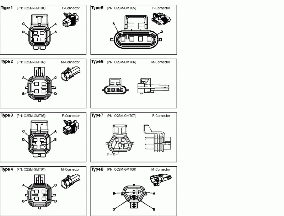
O2 Simulator Tester GM 4 Wire General Motors 1996 2003
The image title is O2 Simulator Tester GM 4 Wire General Motors 1996 2003, features dimensions of width 1158 px and height 880 px, with a file size of 1158 x 880. This image image/gif type visual are source from www.afterthoughtsauto.com.
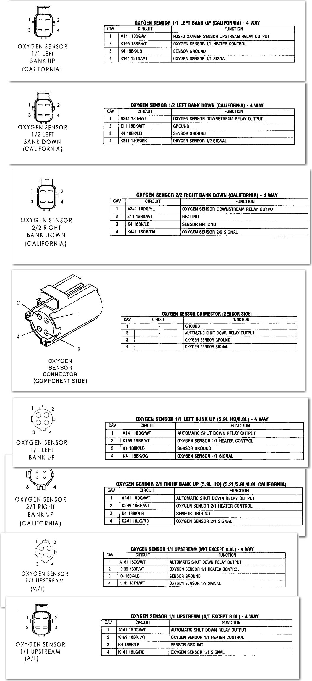
Dodge Ram 1500 O2 Sensor Wiring Q A On 4 Wire Diagrams
The image title is Dodge Ram 1500 O2 Sensor Wiring Q A On 4 Wire Diagrams, features dimensions of width 1056 px and height 2307 px, with a file size of 1056 x 2307. This image image/jpeg type visual are source from www.justanswer.com
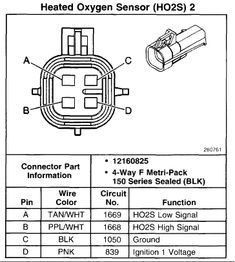
Oxygen Sensor Wiring Diagram For Toyota
The image title is Oxygen Sensor Wiring Diagram For Toyota, features dimensions of width 235 px and height 262 px, with a file size of 235 x 262. This image image/jpeg type visual are source from id.pinterest.com.
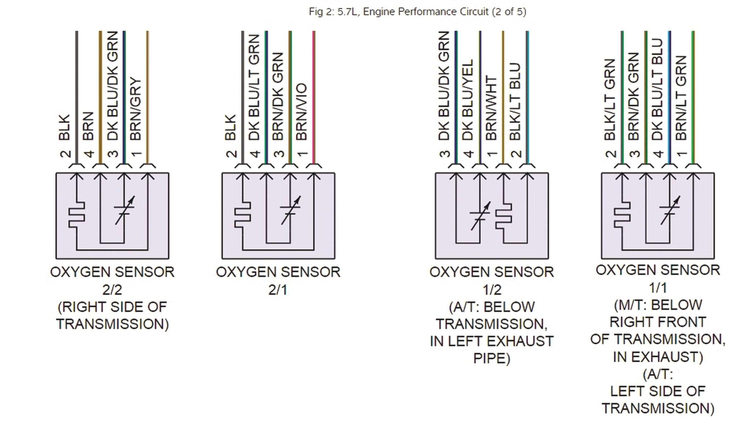
Tracing Sensor Wiring And Checking For Lazy Sensors Issuu
The image title is Tracing Sensor Wiring And Checking For Lazy Sensors Issuu, features dimensions of width 2560 px and height 1475 px, with a file size of 2702 x 1557. This image image/jpeg type visual are source from issuu.com.
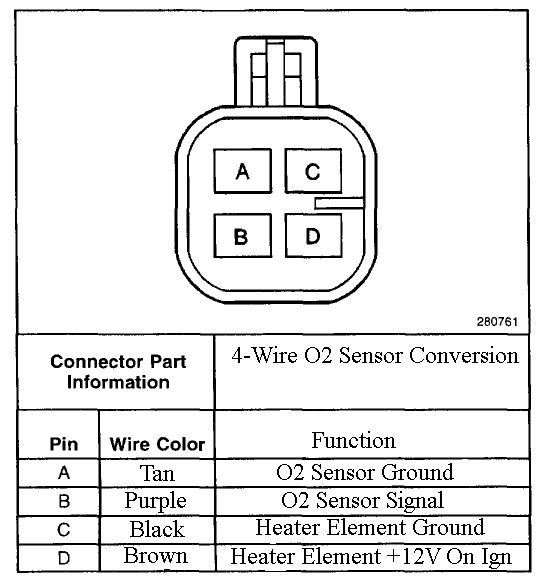
Toyota Oxygen Sensor Pinout 4 Sensor Toyota Oxygen
The image title is Toyota Oxygen Sensor Pinout 4 Sensor Toyota Oxygen, features dimensions of width 560 px and height 585 px, with a file size of 560 x 585.
The images on this page, sourced from Google for educational purposes, may be copyrighted. If you own an image and wish its removal or have copyright concerns, please contact us. We aim to promptly address these issues in compliance with our copyright policy and DMCA standards. Your cooperation is appreciated.
Related Keywords to 4 Wire Oxygen Sensor Wiring Diagram:
4 wire lambda sensor wiring diagram,4 wire o2 sensor wiring diagram,4 wire oxygen sensor wiring diagram,4 wire oxygen sensor wiring diagram ford,4 wire oxygen sensor wiring diagram pdf
