Table of Contents
Exploring the Value of 4 Wire Motor Wiring Diagram
Exploring the Value of 4 Wire Motor Wiring Diagram
When it comes to electrical systems, having a clear and comprehensive wiring diagram is essential for successful installation and maintenance. In the world of motors, a 4 wire motor wiring diagram plays a crucial role in ensuring that the motor functions efficiently and safely. Understanding how to interpret and implement this diagram can make a significant difference in the performance and longevity of the motor. Let’s delve into the intricacies of 4 wire motor wiring diagrams and uncover their value in various applications.
The Basics of 4 Wire Motor Wiring Diagram
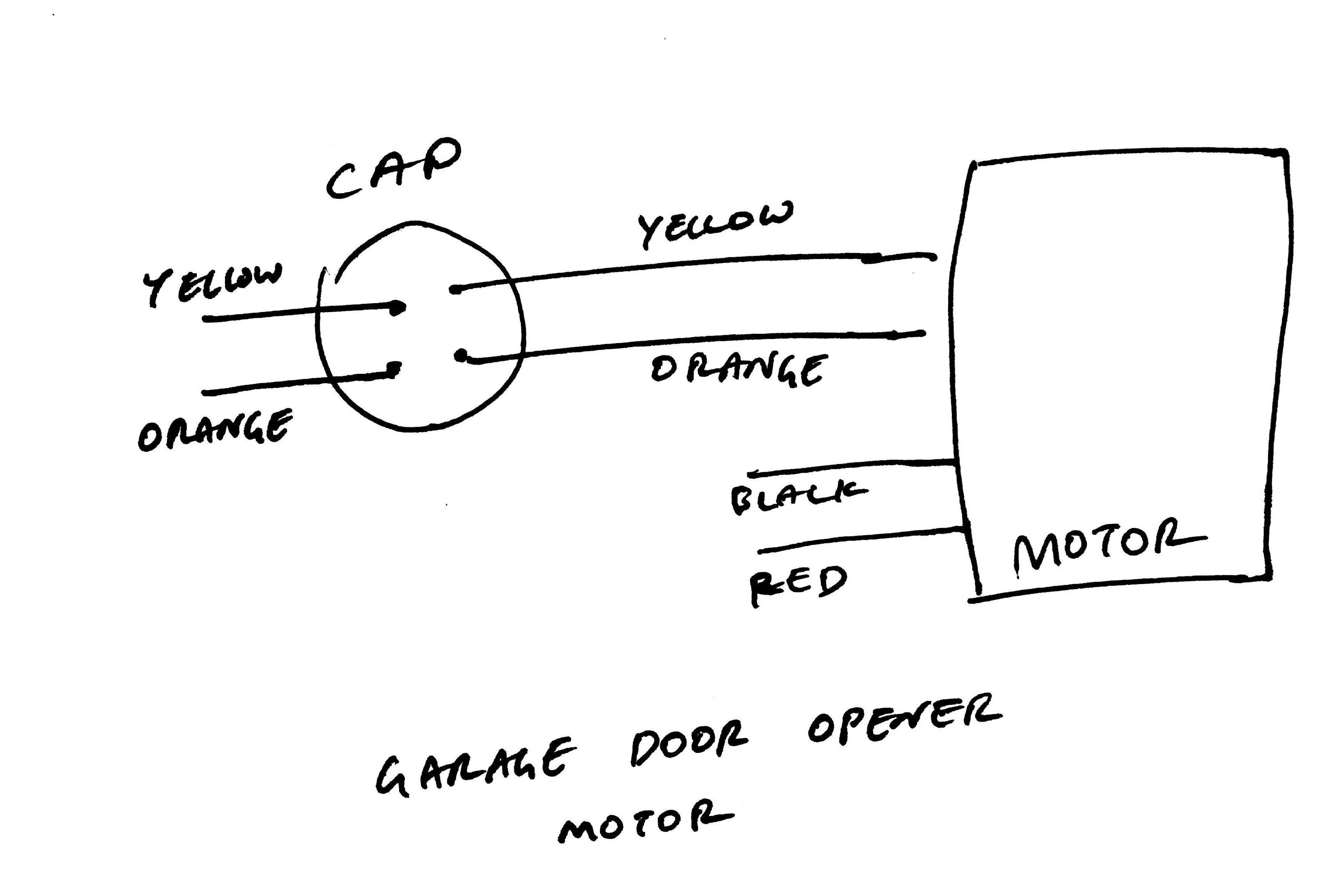
A 4 wire motor wiring diagram outlines the connections between the motor’s terminals and the power source. It provides a detailed map of how the motor should be wired to operate correctly, identifying the phase, neutral, and ground connections. By following the diagram accurately, electricians and technicians can ensure that the motor operates smoothly and safely, reducing the risk of malfunctions or accidents.
Key Components of a 4 Wire Motor Wiring Diagram
Phase Terminals: These terminals are where the power supply is connected to the motor, providing the necessary electrical energy for operation.
Neutral Terminal: The neutral terminal completes the circuit and ensures a stable flow of electricity within the motor.
Ground Terminal: The ground terminal serves as a safety measure, protecting the motor and individuals from electrical hazards.
Applications of 4 Wire Motor Wiring Diagram
4 wire motor wiring diagrams are commonly used in various industries and settings, including HVAC systems, industrial machinery, and automotive applications. These diagrams are invaluable tools for technicians and engineers working with motors, enabling them to troubleshoot issues, perform maintenance tasks, and install new equipment with precision.
Tips for Interpreting and Implementing 4 Wire Motor Wiring Diagram
Always refer to the specific diagram provided by the motor manufacturer to ensure accuracy.
Double-check all connections before powering up the motor to prevent any potential issues.
Follow safety protocols and guidelines when working with electrical systems to avoid accidents.
Conclusion
In conclusion, a 4 wire motor wiring diagram is a valuable resource for anyone working with electric motors. By understanding the components, applications, and best practices associated with these diagrams, individuals can ensure the efficient and safe operation of motors in various settings. Whether you are a seasoned technician or a novice enthusiast, mastering the intricacies of 4 wire motor wiring diagrams can elevate your skills and knowledge in the field of electrical engineering.
Related to 4 Wire Motor Wiring Diagram
- 4 Wire Fuel Pump Wiring Diagram
- 4 Wire Lambda Sensor Wiring Diagram
- 4 Wire Led Light Wiring Diagram
- 4 Wire Light Fixture Wiring Diagram
- 4 Wire Mobile Home Wiring Diagram
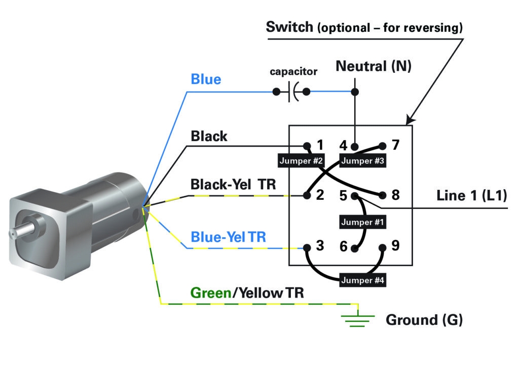
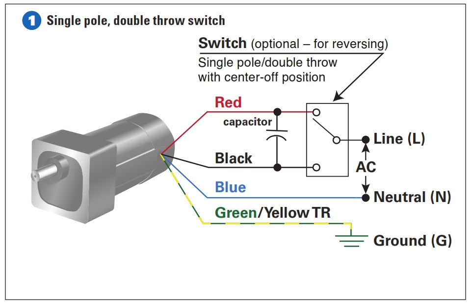
How To Connect A Reversing Switch To A 3 Or 4 Wire PSC Gearmotor Bodine Gearmotor Blog
The image title is How To Connect A Reversing Switch To A 3 Or 4 Wire PSC Gearmotor Bodine Gearmotor Blog, features dimensions of width 1024 px and height 747 px, with a file size of 1024 x 747 px. This image image/jpeg type visual are source from www.bodine-electric.com.
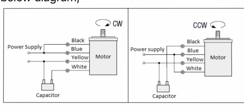
4 Pole Single Phase AC Motor Wiring Electric Motors Generators Engineering Eng Tips
The image title is 4 Pole Single Phase AC Motor Wiring Electric Motors Generators Engineering Eng Tips, features dimensions of width 800 px and height 364 px, with a file size of 800 x 364 px. This image image/jpeg type visual are source from www.eng-tips.com.
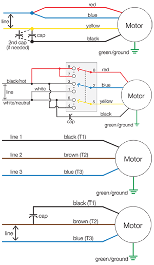
Motor Wiring Diagrams Groschopp
The image title is Motor Wiring Diagrams Groschopp, features dimensions of width 300 px and height 516 px, with a file size of 300 x 516. This image image/png type visual are source from www.groschopp.com.
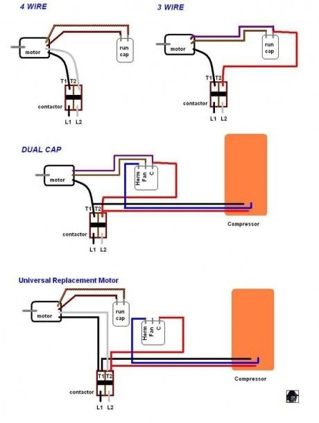
4 Wire Motor Wiring Diagram Ac Fan Fan Motor Attic Fan
The image title is 4 Wire Motor Wiring Diagram Ac Fan Fan Motor Attic Fan, features dimensions of width 460 px and height 610 px, with a file size of 460 x 610. This image image/jpeg type visual are source from www.pinterest.com.
H Bridge Wiring For A 4 Wire AC Motor Electrical Engineering Stack Exchange
The image title is H Bridge Wiring For A 4 Wire AC Motor Electrical Engineering Stack Exchange, features dimensions of width 3156 px and height 2128 px, with a file size of 3156 x 2128. This image image/png type visual are source from electronics.stackexchange.com
How To Connect A Reversing Switch To A 3 Or 4 Wire PSC Gearmotor Bodine Electric Gearmotor Blog
The image title is How To Connect A Reversing Switch To A 3 Or 4 Wire PSC Gearmotor Bodine Electric Gearmotor Blog, features dimensions of width 962 px and height 622 px, with a file size of 962 x 622. This image image/jpeg type visual are source from gearmotorblog.wordpress.com.
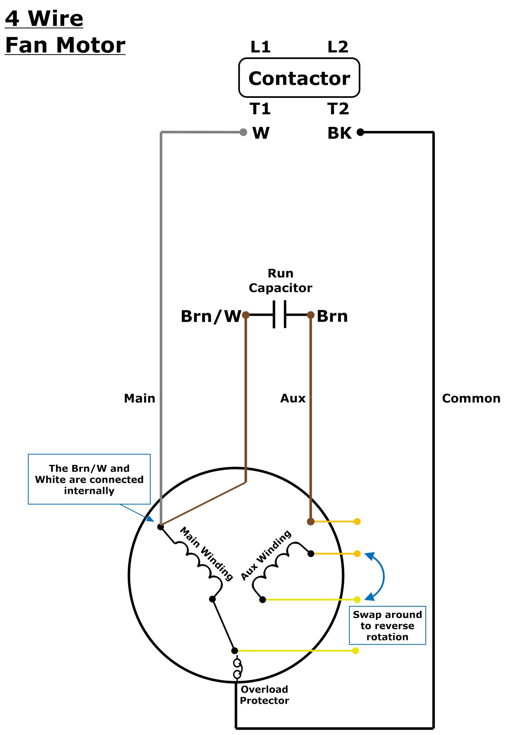
3 Or 4 Wire Condenser Fan Motor Wiring Johnstone Supply Support
The image title is 3 Or 4 Wire Condenser Fan Motor Wiring Johnstone Supply Support, features dimensions of width 1762 px and height 2560 px, with a file size of 2837 x 4123. This image image/jpeg type visual are source from support.johnstonehvac.biz.
How To Wire A Permanent Split Capacitor PSC 4 Wire Reversible AC Motor Or Gearmotor Bodine Gearmotor Blog
The image title is How To Wire A Permanent Split Capacitor PSC 4 Wire Reversible AC Motor Or Gearmotor Bodine Gearmotor Blog, features dimensions of width 487 px and height 421 px, with a file size of 487 x 421.
The images on this page, sourced from Google for educational purposes, may be copyrighted. If you own an image and wish its removal or have copyright concerns, please contact us. We aim to promptly address these issues in compliance with our copyright policy and DMCA standards. Your cooperation is appreciated.
Related Keywords to 4 Wire Motor Wiring Diagram:
4 wire fan motor wiring diagram,4 wire motor wiring diagram,4 wire motor wiring diagram pdf,4 wire wiper motor wiring diagram,4-wire stepper motor wiring diagram
