Table of Contents
The Importance of 3 Wire Maf Sensor Wiring Diagram
In the realm of automotive engineering, precision and accuracy are paramount. A critical component in this field is the Mass Airflow (MAF) sensor, which plays a crucial role in monitoring and regulating the air intake of an engine. To ensure seamless functionality and optimal performance, understanding the wiring diagram of a 3 Wire MAF sensor is essential. This diagram serves as a blueprint for connecting the sensor to the vehicle’s electrical system, enabling technicians to troubleshoot issues, make adjustments, and conduct repairs effectively.
Benefits of a Well-Defined Wiring Diagram
A comprehensive 3 Wire MAF sensor wiring diagram provides numerous advantages for automotive professionals and enthusiasts alike. By adhering to a structured schematic layout, individuals can easily identify the various components of the sensor and understand how they interact with the vehicle’s electrical system. This clarity facilitates diagnostic procedures, simplifies maintenance tasks, and enhances overall efficiency in handling sensor-related issues.
Key Components of the Wiring Diagram
When delving into a 3 Wire MAF sensor wiring diagram, it is crucial to familiarize oneself with the key components outlined within the schematic. These components typically include the power supply, ground connection, signal wire, and any additional features specific to the sensor model. Understanding the function of each element and their respective connections is vital for ensuring proper installation, calibration, and troubleshooting of the sensor.
Proper Wiring Techniques
To harness the full potential of a 3 Wire MAF sensor wiring diagram, it is imperative to employ proper wiring techniques during installation and maintenance procedures. This involves utilizing the appropriate tools, following recommended guidelines, and adhering to safety protocols to prevent any mishaps or malfunctions. By mastering these techniques, individuals can optimize the performance of the sensor and uphold the integrity of the vehicle’s electrical system.
Common Issues and Solutions
Despite the meticulous planning and implementation of a wiring diagram, occasional issues may arise with the 3 Wire MAF sensor. These issues could stem from faulty connections, damaged components, or external factors affecting sensor performance. By referencing the wiring diagram and leveraging troubleshooting skills, individuals can pinpoint the root cause of the problem and apply relevant solutions to rectify the issue effectively.
Conclusion
In conclusion, the value of a 3 Wire MAF sensor wiring diagram cannot be overstated in the realm of automotive engineering. By utilizing this schematic as a guiding tool, individuals can navigate the intricacies of sensor installation, maintenance, and troubleshooting with confidence and precision. The insights gleaned from a well-defined wiring diagram empower technicians and enthusiasts to optimize sensor performance, enhance vehicle efficiency, and uphold industry standards in automotive technology.
Related to 3 Wire Maf Sensor Wiring Diagram
- 3 Wire Gm Alternator Wiring Diagram
- 3 Wire Headlight Wiring Diagram
- 3 Wire Led Light Bar Wiring Diagram
- 3 Wire Led Light Wiring Diagram
- 3 Wire Led Tail Light Wiring Diagram
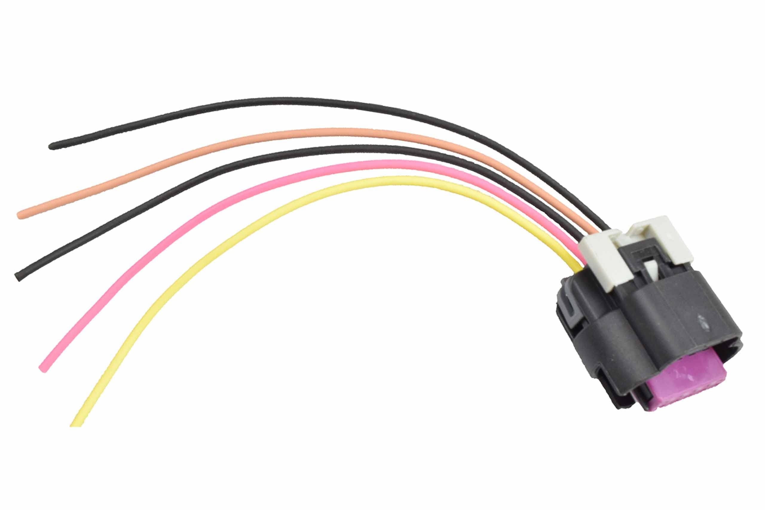
LS3 LS7 Mass Air Flow Connector Pigtail
The image title is LS3 LS7 Mass Air Flow Connector Pigtail, features dimensions of width 2000 px and height 1539 px, with a file size of 2000 x 1539 px. This image image/png type visual are source from bp-automotive.com.
Amazon ICT Billet LS Mass Air Flow Connector 5 Wire Pigtail Gen 3 WPMAF30 Automotive
The image title is Amazon ICT Billet LS Mass Air Flow Connector 5 Wire Pigtail Gen 3 WPMAF30 Automotive, features dimensions of width 2560 px and height 1707 px, with a file size of 2560 x 1707 px. This image image/jpeg type visual are source from www.amazon.com.
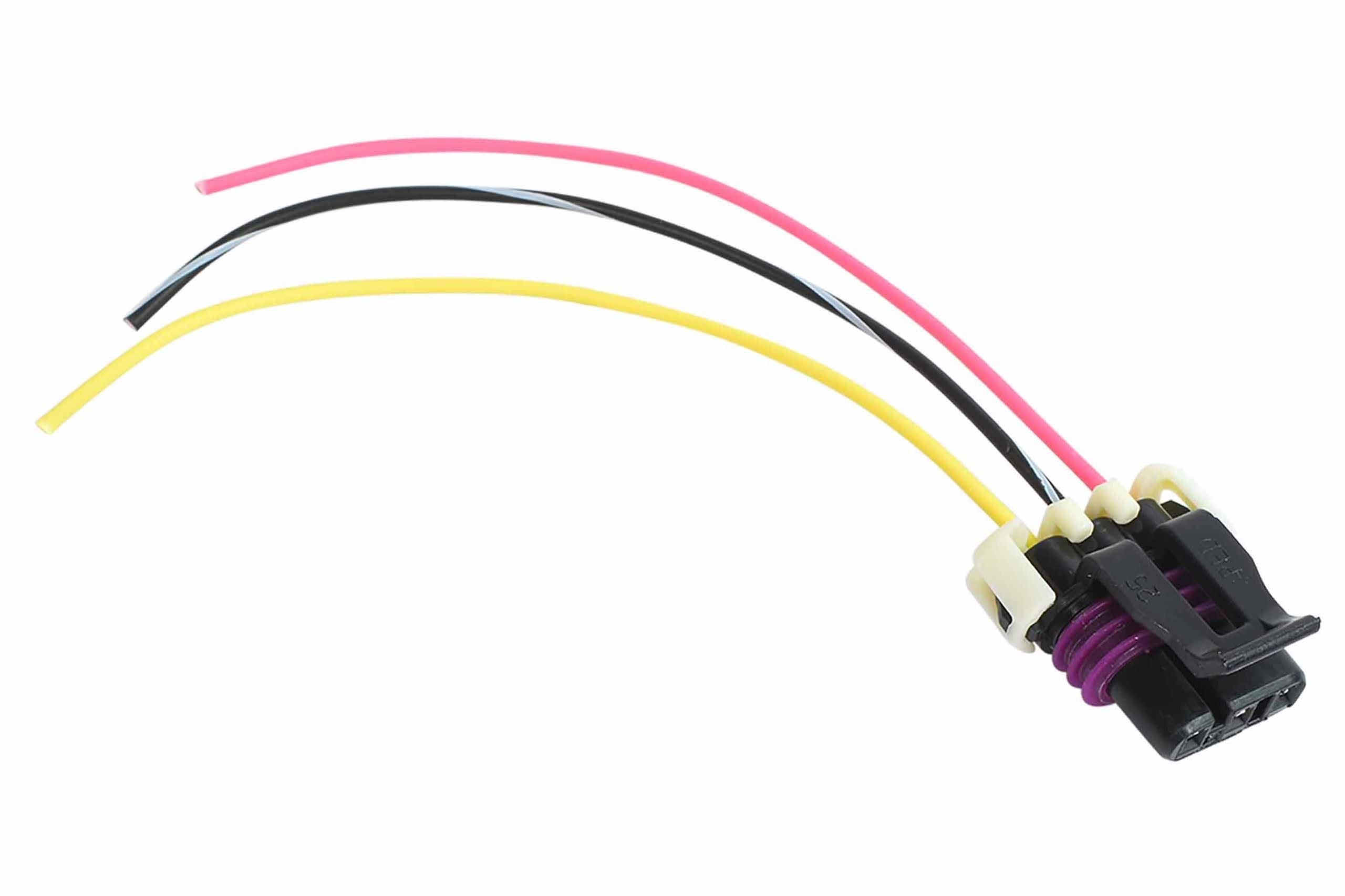
Amazon ICT Billet Wire Harness Pigtail Connector LS Gen 3 MAF Mass Air Flow Intake Sensor 3 Wire Compatible With GM RPO Codes LS1 5 7L Camaro Corvette 1997 To 2000WPMAF31 Automotive
The image title is Amazon ICT Billet Wire Harness Pigtail Connector LS Gen 3 MAF Mass Air Flow Intake Sensor 3 Wire Compatible With GM RPO Codes LS1 5 7L Camaro Corvette 1997 To 2000WPMAF31 Automotive, features dimensions of width 2560 px and height 1706 px, with a file size of 2560 x 1706. This image image/jpeg type visual are source from www.amazon.com.
LS1 3 MAF Wire Harness To LS3 5 Wire MAF Sensor Adapter LS7 Mass Air Flow Meter EBay
The image title is LS1 3 MAF Wire Harness To LS3 5 Wire MAF Sensor Adapter LS7 Mass Air Flow Meter EBay, features dimensions of width 1000 px and height 1000 px, with a file size of 1000 x 1000. This image image/jpeg type visual are source from www.ebay.com.
LS1 LT1 GM 3 Wire MAF Mass Air Flow Sensor Wiring Connector Pigtail EBay
The image title is LS1 LT1 GM 3 Wire MAF Mass Air Flow Sensor Wiring Connector Pigtail EBay, features dimensions of width 400 px and height 326 px, with a file size of 400 x 326. This image image/jpeg type visual are source from www.ebay.com
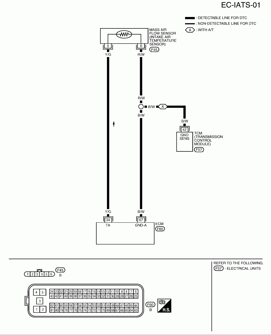
Nissan MAF Sensor Wiring Diagram Q A For 3 4 And 5 Wire Mass Air Flow
The image title is Nissan MAF Sensor Wiring Diagram Q A For 3 4 And 5 Wire Mass Air Flow, features dimensions of width 1072 px and height 1321 px, with a file size of 1072 x 1321. This image image/gif type visual are source from www.justanswer.com.
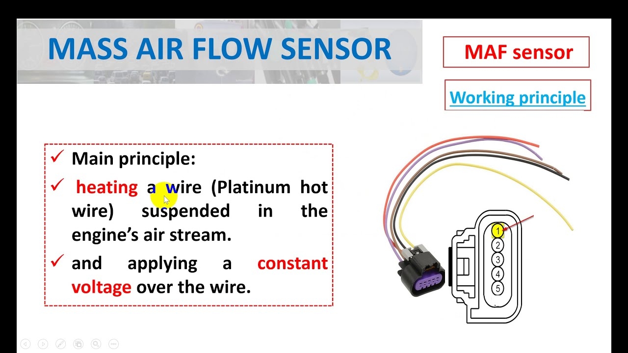
Mass Air Flow Sensor Hot Wire Symptoms Of A Bad MAF Sensor YouTube
The image title is Mass Air Flow Sensor Hot Wire Symptoms Of A Bad MAF Sensor YouTube, features dimensions of width 1280 px and height 720 px, with a file size of 1280 x 720. This image image/jpeg type visual are source from m.youtube.com.
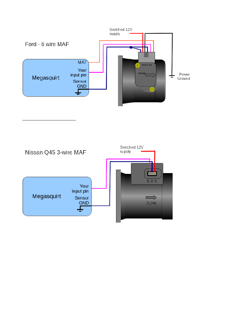
MS3XV357 Hardware 1 5 Page 32
The image title is MS3XV357 Hardware 1 5 Page 32, features dimensions of width 893 px and height 1188 px, with a file size of 893 x 1188.
The images on this page, sourced from Google for educational purposes, may be copyrighted. If you own an image and wish its removal or have copyright concerns, please contact us. We aim to promptly address these issues in compliance with our copyright policy and DMCA standards. Your cooperation is appreciated.
Related Keywords to 3 Wire Maf Sensor Wiring Diagram:
3 wire maf sensor wiring diagram,3 wire mass air flow sensor wiring diagram,how does a hot wire maf sensor work,how to test 3 wire maf sensor,how to wire a 3 wire sensor
