Table of Contents
Exploring the 3 Wire Bilge Pump Wiring Diagram: A Comprehensive Guide
Exploring the 3 Wire Bilge Pump Wiring Diagram: A Comprehensive Guide
When it comes to ensuring the safety and smooth operation of your boat, having a reliable bilge pump is essential. A properly wired bilge pump can mean the difference between a dry bilge and a potential disaster. Understanding the intricacies of the 3 wire bilge pump wiring diagram is crucial for any boat owner or enthusiast looking to maintain their vessel in top condition. In this comprehensive guide, we will delve into the details of the 3 wire bilge pump wiring diagram, providing you with valuable insights and practical tips to navigate this critical aspect of marine electrical systems.
The Basics of Bilge Pump Wiring
Before we delve into the specifics of the 3 wire bilge pump wiring diagram, it’s important to understand the basics of bilge pump wiring. Bilge pumps are responsible for removing excess water from the bilge area of a boat, helping to prevent flooding and damage. Proper wiring ensures that the bilge pump operates efficiently and reliably when needed.
Key Components of a Bilge Pump System
A typical bilge pump system consists of several key components, including the bilge pump itself, a float switch, and a control panel. The bilge pump is the main component responsible for pumping out water, while the float switch activates the pump when water levels rise. The control panel provides a central hub for monitoring and controlling the bilge pump system.
Importance of Proper Wiring
Proper wiring is essential for the effective operation of a bilge pump system. Incorrect wiring can lead to malfunctions, inefficiencies, or even system failures, putting your boat at risk. Understanding the wiring diagram of your bilge pump system is crucial for troubleshooting issues, making upgrades, or performing maintenance tasks.
Understanding the 3 Wire Bilge Pump Wiring Diagram
The 3 wire bilge pump wiring diagram is a standard configuration used in many marine applications. This wiring setup typically includes three wires: positive (+), negative (-), and an automatic float switch wire. The positive and negative wires connect to the power source, while the automatic float switch wire is connected to the float switch for automatic operation.
Step-by-Step Guide to Wiring a 3 Wire Bilge Pump
Identify the positive (+) and negative (-) wires of the bilge pump.
Connect the positive wire to the positive terminal of the power source.
Connect the negative wire to the negative terminal of the power source.
Connect the automatic float switch wire to the float switch.
Tips for Troubleshooting and Maintenance
Regularly inspect the wiring connections for signs of wear or corrosion.
Test the bilge pump system periodically to ensure proper operation.
Consult the manufacturer’s wiring diagram for specific guidelines and recommendations.
Conclusion
In conclusion, understanding the 3 wire bilge pump wiring diagram is essential for maintaining a safe and efficient bilge pump system on your boat. By following the guidelines outlined in this comprehensive guide, you can confidently wire your bilge pump and troubleshoot any issues that may arise. Remember, proper wiring is the key to a reliable bilge pump system that can protect your vessel from potential water damage. Stay informed, stay prepared, and sail with confidence!
Related to 3 Wire Bilge Pump Wiring Diagram
- 3 Wire 700r4 Wiring Diagram
- 3 Wire Ac Dual Capacitor Wiring Diagram
- 3 Wire Alternator Wiring Diagram
- 3 Wire Alternator Wiring Diagram Ford
- 3 Wire Aux Cable Wiring Diagram
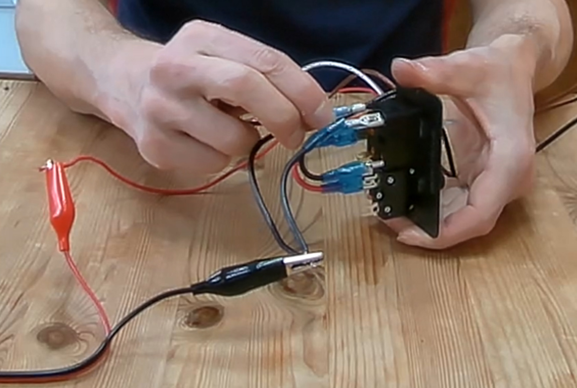
How Do You Wire A Bilge Pump Boat Fittings
The image title is How Do You Wire A Bilge Pump Boat Fittings, features dimensions of width 1149 px and height 774 px, with a file size of 1149 x 774 px. This image image/png type visual are source from www.boatfittings.co.uk.
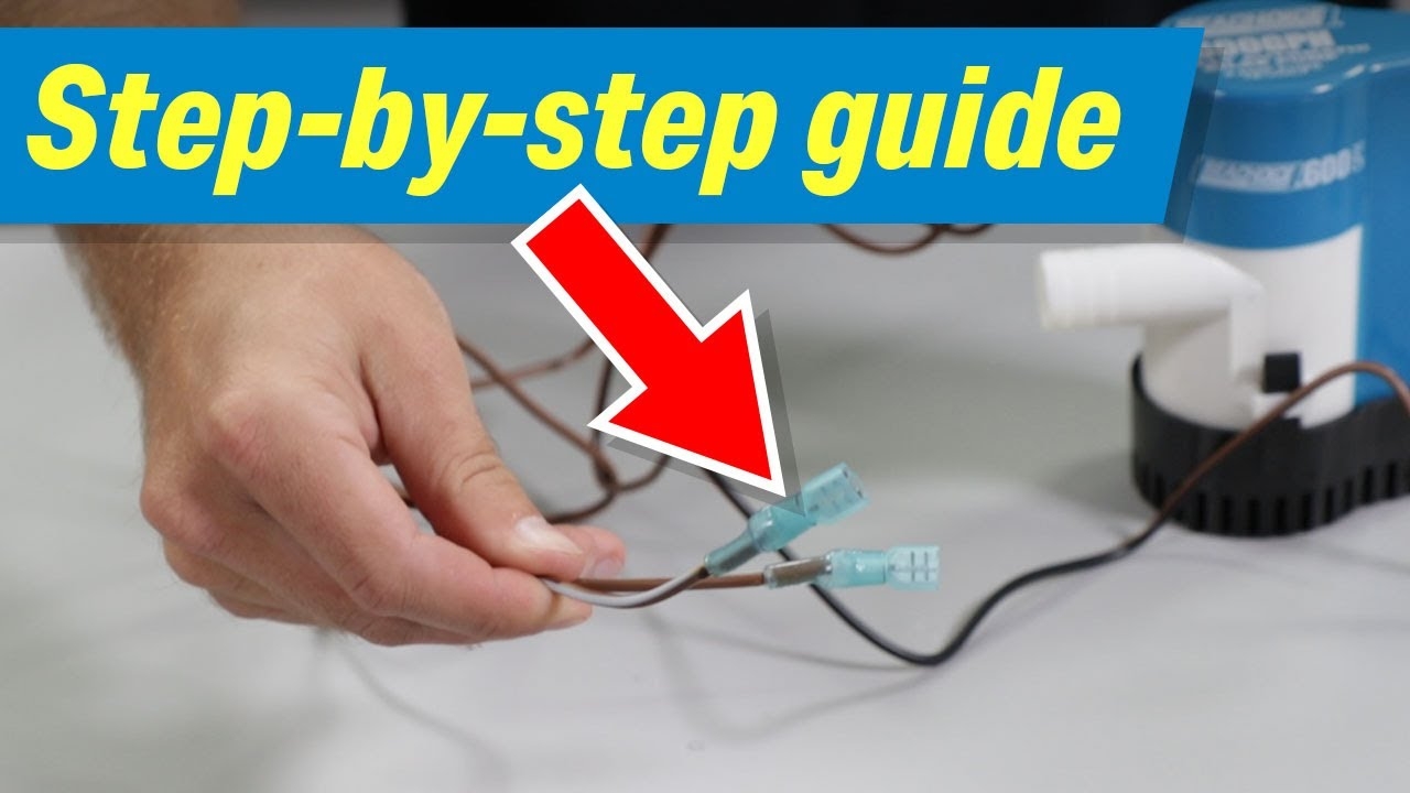
How To Wire An Automatic Bilge Pump To A 3 Position Switch YouTube
The image title is How To Wire An Automatic Bilge Pump To A 3 Position Switch YouTube, features dimensions of width 1280 px and height 720 px, with a file size of 1280 x 720 px. This image image/jpeg type visual are source from m.youtube.com.
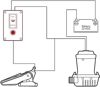
Amazon 3 Position Bilge Pump Rocker Switch Panel Automatic Off Manual Three Positions To Control The Pumps DC 12V 24V With 10A Fuse Circuit Breaker Auto Hand Driven With LED Indicator For
The image title is Amazon 3 Position Bilge Pump Rocker Switch Panel Automatic Off Manual Three Positions To Control The Pumps DC 12V 24V With 10A Fuse Circuit Breaker Auto Hand Driven With LED Indicator For, features dimensions of width 350 px and height 307 px, with a file size of 350 x 307. This image image/jpeg type visual are source from www.amazon.com.
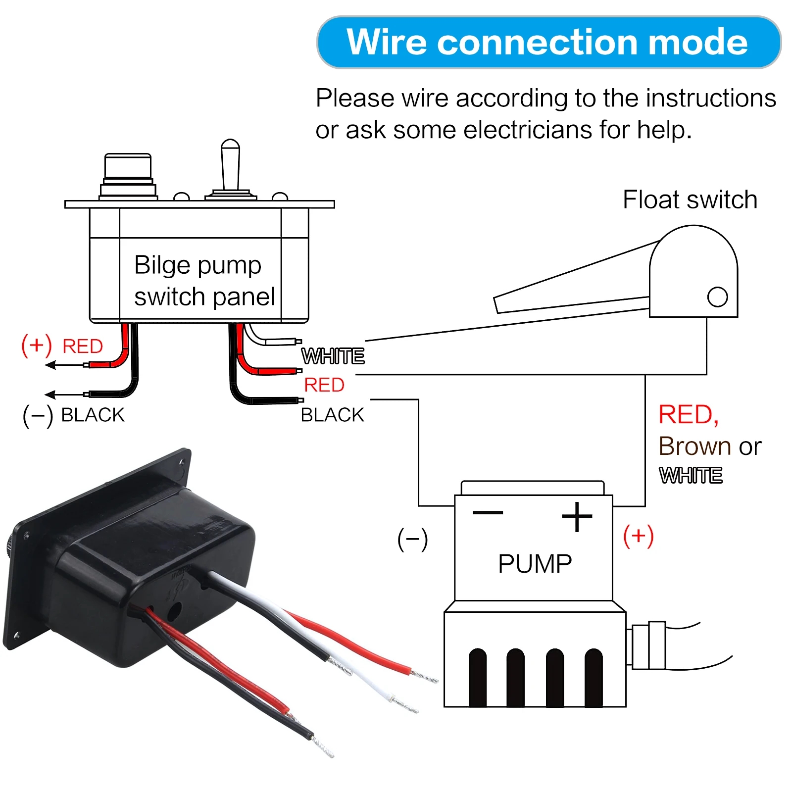
12V Bilge Pump Control Switch Panel 3 Way Manual Off Auto With LED Indicator 5A Fuse For Yacht Camper Truck Marine Boat AliExpress
The image title is 12V Bilge Pump Control Switch Panel 3 Way Manual Off Auto With LED Indicator 5A Fuse For Yacht Camper Truck Marine Boat AliExpress, features dimensions of width 1600 px and height 1600 px, with a file size of 1600 x 1600. This image image/jpeg type visual are source from s.click.aliexpress.com.
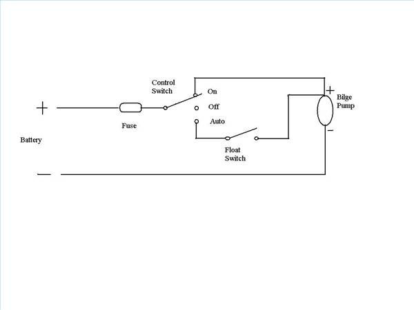
Bilge Pump Wiring Schematic Bilge Pump With Float Sw On Off Auto Switch Cruisers Sailing Photo Gallery
The image title is Bilge Pump Wiring Schematic Bilge Pump With Float Sw On Off Auto Switch Cruisers Sailing Photo Gallery, features dimensions of width 600 px and height 450 px, with a file size of 600 x 450. This image image/jpeg type visual are source from www.cruisersforum.com
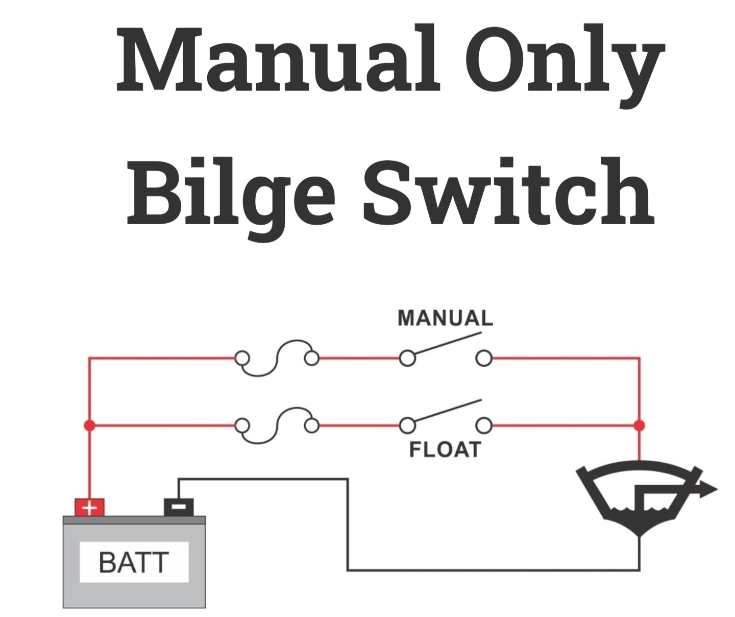
Hello Connecting A Digital Input For A Noob Victron Community
The image title is Hello Connecting A Digital Input For A Noob Victron Community, features dimensions of width 1440 px and height 1208 px, with a file size of 1440 x 1208. This image image/jpeg type visual are source from community.victronenergy.com.
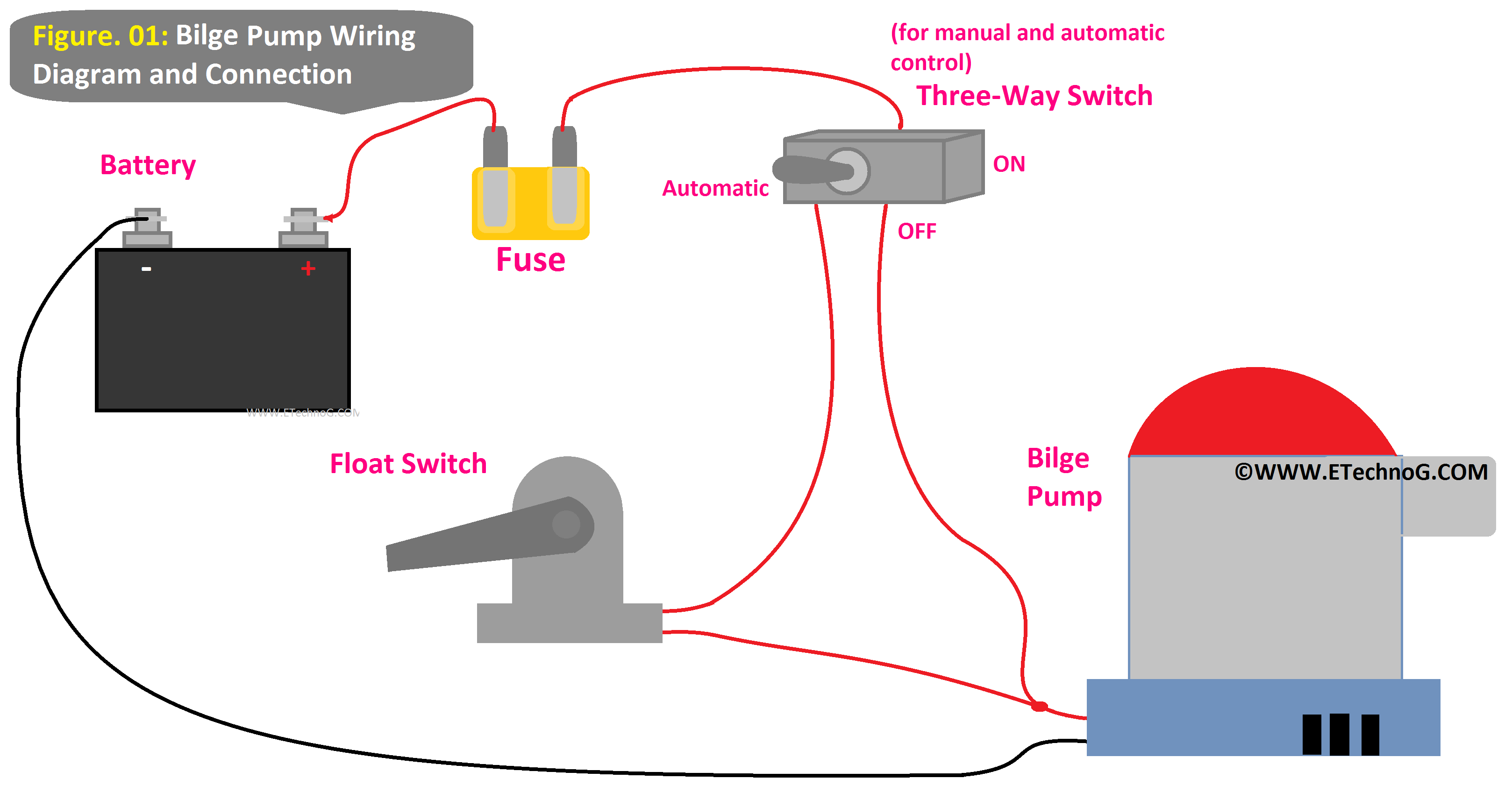
Bilge Pump Wiring Diagram And Connection In Boat Electrical Diagram Electrical Circuit Diagram Three Way Switch
The image title is Bilge Pump Wiring Diagram And Connection In Boat Electrical Diagram Electrical Circuit Diagram Three Way Switch, features dimensions of width 3236 px and height 1728 px, with a file size of 3236 x 1728. This image image/png type visual are source from www.pinterest.com.
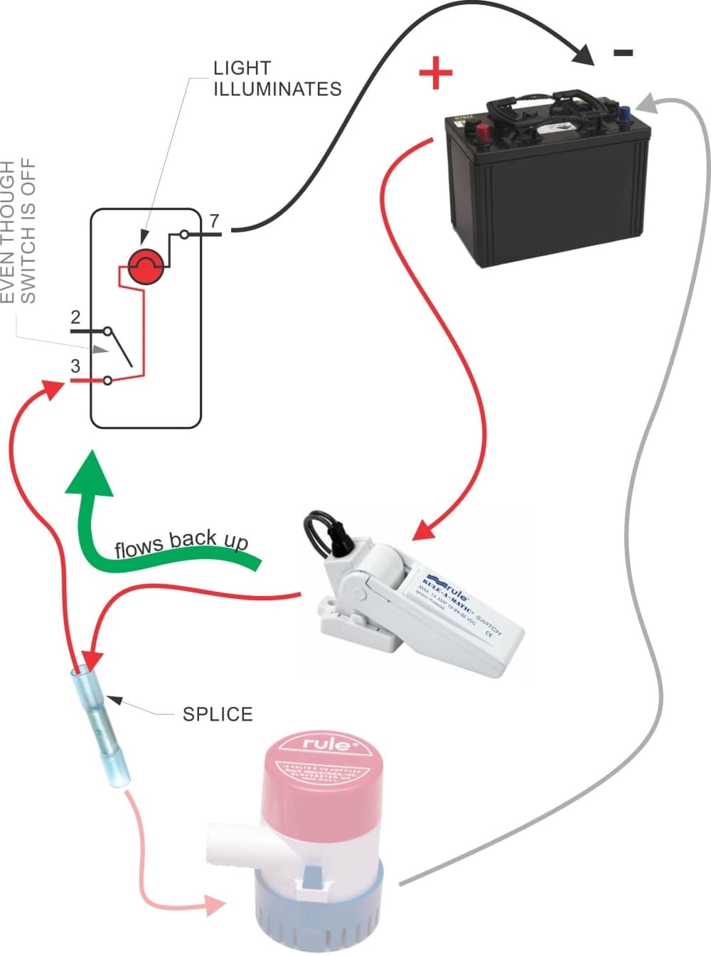
How To Wire A Bilge Pump ON OFF Bilge Switch New Wire Marine
The image title is How To Wire A Bilge Pump ON OFF Bilge Switch New Wire Marine, features dimensions of width 1000 px and height 1344 px, with a file size of 1000 x 1344.
The images on this page, sourced from Google for educational purposes, may be copyrighted. If you own an image and wish its removal or have copyright concerns, please contact us. We aim to promptly address these issues in compliance with our copyright policy and DMCA standards. Your cooperation is appreciated.
Related Keywords to 3 Wire Bilge Pump Wiring Diagram:
3 wire bilge pump wiring diagram,automatic 3 wire bilge pump wiring diagram,how do you wire a 3 wire bilge pump,rule 3 wire bilge pump wiring diagram
