Table of Contents
Exploring the Intricacies of 24v Zone Valve Wiring Diagram
The Value of 24v Zone Valve Wiring Diagram
When it comes to ensuring optimal functionality of HVAC systems, having a comprehensive understanding of the wiring diagram is crucial. Among the various components that make up a heating or cooling system, zone valves play a pivotal role in regulating the flow of heated or cooled air to specific areas. In this context, a 24v zone valve wiring diagram serves as a roadmap that guides technicians and DIY enthusiasts alike in connecting the intricate network of wires effectively. By delving into the nuances of this diagram, one can unlock a wealth of knowledge that empowers them to troubleshoot, repair, or install zone valves with precision and efficiency.
Understanding the Basics
At the core of any 24v zone valve wiring diagram lies a series of wires that facilitate the transfer of electrical signals to control the opening and closing of the valve. These signals are typically supplied by a low-voltage transformer, commonly rated at 24 volts, which serves as the power source for the zone valve system. By deciphering the color codes and terminal designations within the wiring diagram, individuals can identify the correct connections for each wire, ensuring a seamless integration of the zone valves into the overall HVAC setup.
Key Components and Connections
Within a 24v zone valve wiring diagram, one may encounter various components such as thermostats, aquastats, relays, and end switches, each playing a specific role in the operation of the system. Understanding how these components interact and the significance of their respective connections is essential for troubleshooting issues, optimizing performance, or expanding the capabilities of the zone valve setup. By following the designated wiring paths and terminal points detailed in the diagram, individuals can establish a robust electrical framework that ensures precise control and distribution of air within different zones.
Installation and Troubleshooting Tips
When embarking on the installation of a 24v zone valve system, referring to a comprehensive wiring diagram can streamline the process and minimize the risk of errors. By adhering to industry best practices and manufacturer guidelines, individuals can confidently connect the various components in a logical sequence, testing the system at each stage to verify proper functionality. In the event of malfunctions or discrepancies, the wiring diagram serves as a valuable tool for isolating issues, identifying faulty connections, and rectifying them promptly to restore the system to optimal performance.
Conclusion
In conclusion, the intricate world of 24v zone valve wiring diagrams holds a wealth of information that can transform the way individuals approach HVAC system maintenance, repair, or installation. By engaging with these diagrams with a keen eye for detail and a thirst for knowledge, one can unravel the complexities of zone valve setups, harnessing their full potential to create comfortable and efficient indoor environments. Whether you are a seasoned technician or a DIY enthusiast, mastering the art of interpreting and implementing 24v zone valve wiring diagrams is a skill that promises to elevate your expertise in the realm of HVAC systems.
Related to 24v Zone Valve Wiring Diagram
- 24v Electric Scooter Controller Wiring Diagram
- 24v Hvac Relay Wiring Diagram
- 24v Relay Wiring Diagram
- 24v Trolling Motor Wiring Diagram
- 24v Wiring Diagram For Trolling Motors
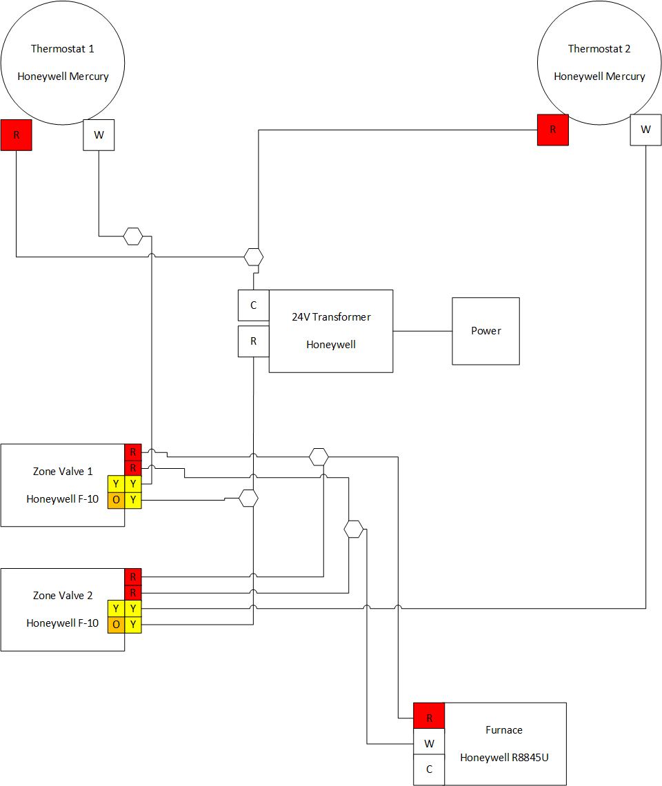
Thermostat How To Connect A New C Wire Home Improvement Stack Exchange
The image title is Thermostat How To Connect A New C Wire Home Improvement Stack Exchange, features dimensions of width 960 px and height 1140 px, with a file size of 960 x 1140 px. This image image/png type visual are source from diy.stackexchange.com.
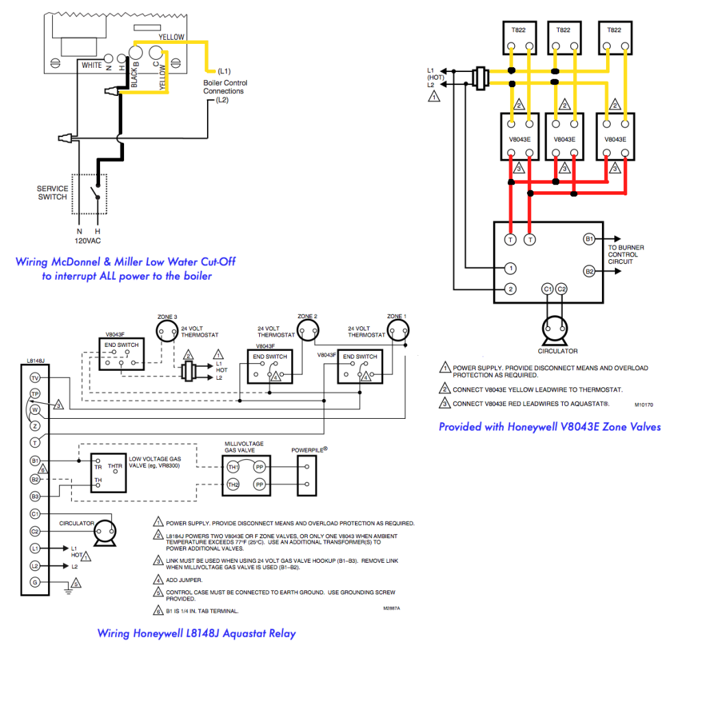
Honeywell Boiler Zone Valves Wiring Wiring 3 Zone With Honeywell L8148J Honeywell V8043E And Low Water Honeywell Thermostat Wiring Low Water
The image title is Honeywell Boiler Zone Valves Wiring Wiring 3 Zone With Honeywell L8148J Honeywell V8043E And Low Water Honeywell Thermostat Wiring Low Water, features dimensions of width 1024 px and height 1024 px, with a file size of 1024 x 1024 px. This image image/png type visual are source from www.pinterest.com.
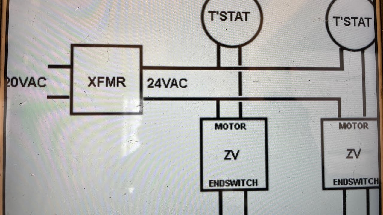
How To Install Wire Honeywell 4 Wire Zone Valve YouTube
The image title is How To Install Wire Honeywell 4 Wire Zone Valve YouTube, features dimensions of width 1280 px and height 720 px, with a file size of 1280 x 720. This image image/jpeg type visual are source from m.youtube.com.
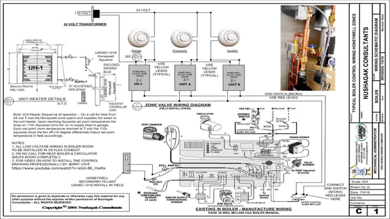
CLICK HERE Updated Corrected Zone Valve Wiring Schematic YouTube
The image title is CLICK HERE Updated Corrected Zone Valve Wiring Schematic YouTube, features dimensions of width 1280 px and height 720 px, with a file size of 1280 x 720. This image image/jpeg type visual are source from www.youtube.com.
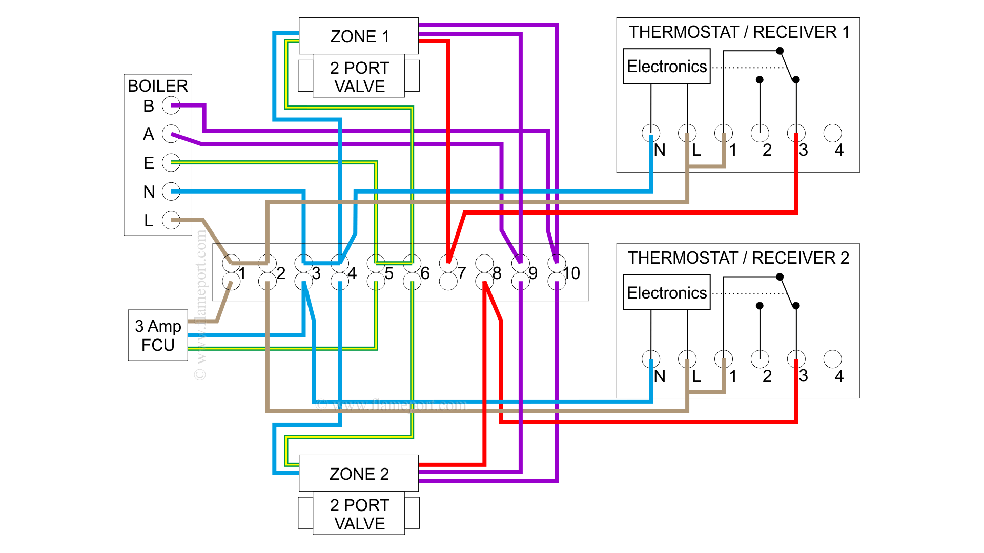
Combination Boiler With 2 Heating Zones Volt Free Switching
The image title is Combination Boiler With 2 Heating Zones Volt Free Switching, features dimensions of width 1920 px and height 1080 px, with a file size of 1920 x 1080. This image image/png type visual are source from flameport.com
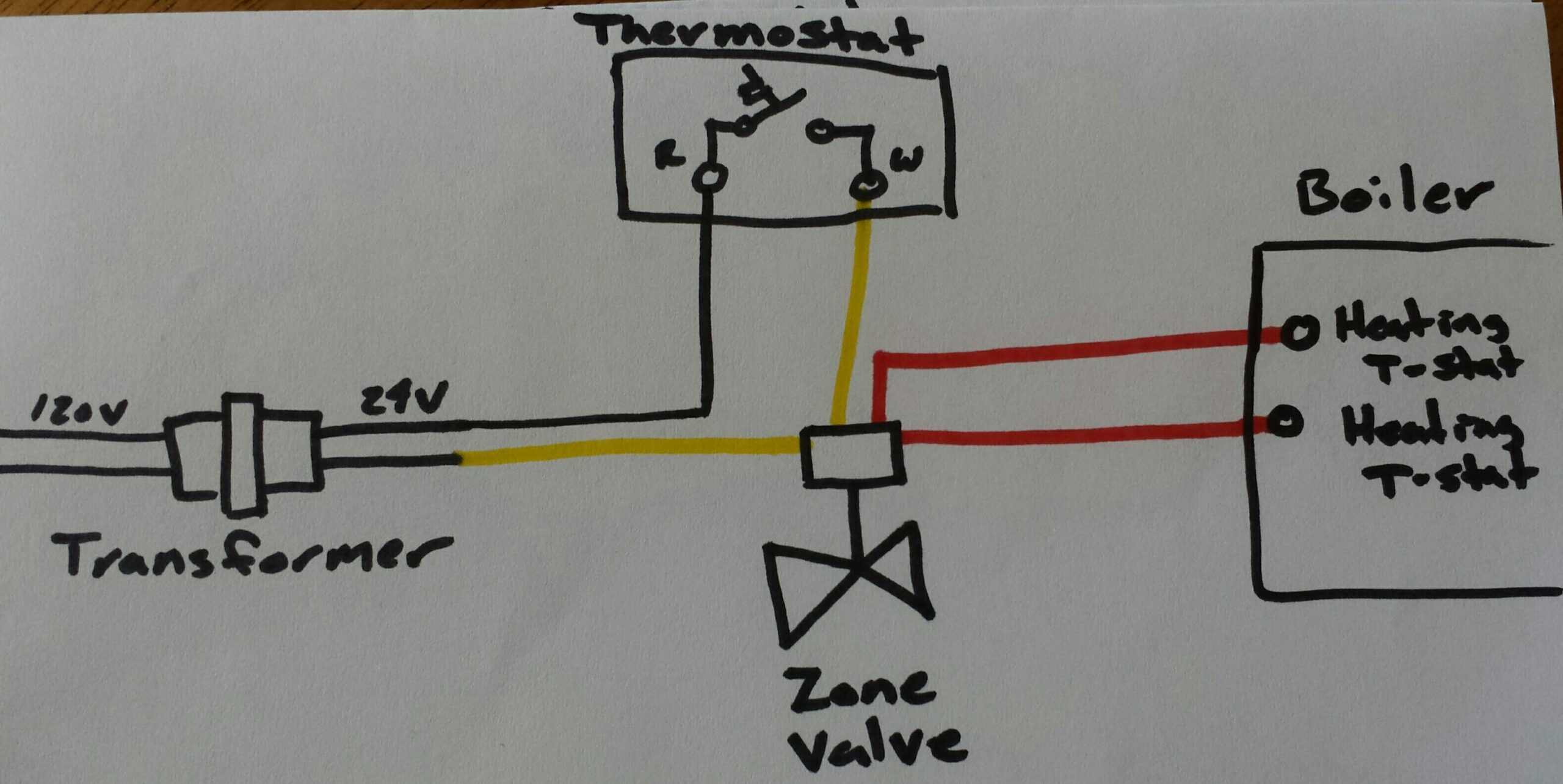
Need Help With Completing Zone Thermostat And Low Pressure Wiring For A Alpine Boiler ALP150 Home Improvement Stack Exchange
The image title is Need Help With Completing Zone Thermostat And Low Pressure Wiring For A Alpine Boiler ALP150 Home Improvement Stack Exchange, features dimensions of width 2560 px and height 1284 px, with a file size of 3157 x 1584. This image image/jpeg type visual are source from diy.stackexchange.com.
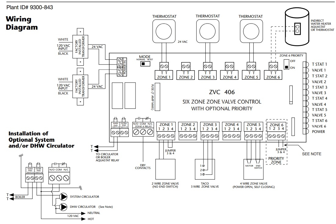
Comfort Calc
The image title is Comfort Calc, features dimensions of width 1101 px and height 733 px, with a file size of 1101 x 733. This image image/jpeg type visual are source from www.comfort-calc.com.
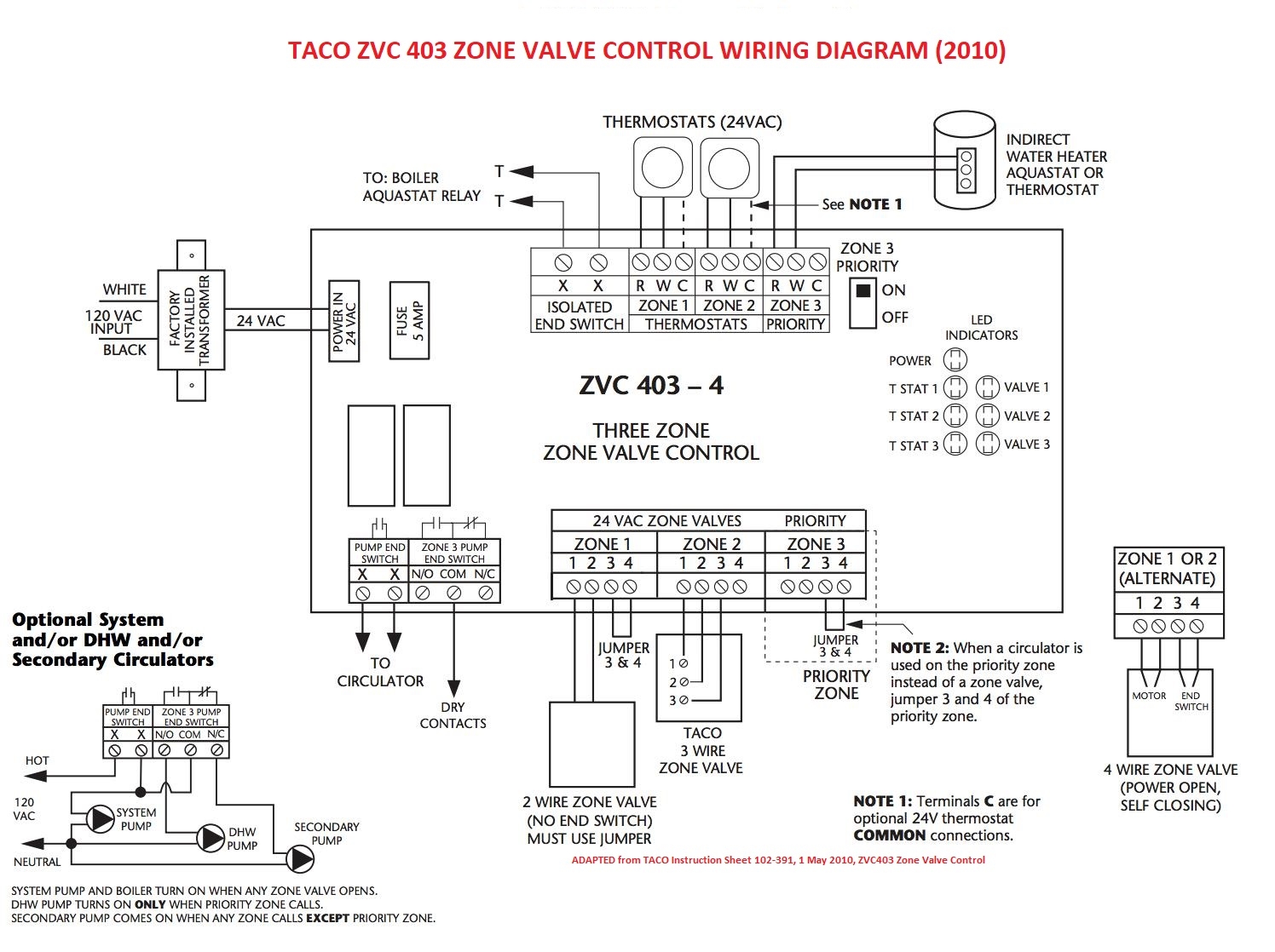
Zone Valve Wiring Manuals Installation Instructions Guide To Heating System Zone Valves Zone Valve Installation Inspection Repair Guide
The image title is Zone Valve Wiring Manuals Installation Instructions Guide To Heating System Zone Valves Zone Valve Installation Inspection Repair Guide, features dimensions of width 1496 px and height 1118 px, with a file size of 1496 x 1118.
The images on this page, sourced from Google for educational purposes, may be copyrighted. If you own an image and wish its removal or have copyright concerns, please contact us. We aim to promptly address these issues in compliance with our copyright policy and DMCA standards. Your cooperation is appreciated.
Related Keywords to 24v Zone Valve Wiring Diagram:
24v zone valve wiring diagram,24v zone valve wiring diagram pdf,honeywell 24 volt zone valve wiring diagram,honeywell 24v zone valve wiring diagram,zone valve wiring explained
