Table of Contents
Exploring the Value of 240 Volt Contactor Wiring Diagram
Exploring the Value of 240 Volt Contactor Wiring Diagram
When it comes to electrical wiring, precision and accuracy are paramount to ensure safety and efficiency. A 240 volt contactor wiring diagram serves as a crucial tool in understanding and implementing the intricate connections required for handling high-voltage systems. This detailed schematic provides a roadmap for electricians and technicians to follow, guiding them through the process of wiring contactors for optimal performance. Let’s delve into the world of 240 volt contactor wiring diagrams to uncover their significance and functionality.
The Basics of 240 Volt Contactor Wiring Diagram
Before delving into the complexities of a 240 volt contactor wiring diagram, it’s essential to grasp the fundamental concepts behind contactors. These electrical relays are designed to control the flow of electricity in a circuit by opening and closing contacts based on external signals. Contactors are commonly used in HVAC systems, industrial machinery, and other high-power applications that require precise control of electrical currents.
Key Components of a 240 Volt Contactor Wiring Diagram
A typical 240 volt contactor wiring diagram includes several key components that are essential for understanding and implementing the wiring connections. These components may vary based on the specific application and manufacturer, but some common elements include:
Power supply connections
Control circuit connections
Load connections
Overload protection devices
Benefits of Using a 240 Volt Contactor Wiring Diagram
The advantages of utilizing a 240 volt contactor wiring diagram are manifold, ranging from improved safety to enhanced troubleshooting capabilities. By following a well-drawn wiring diagram, technicians can ensure that all connections are made correctly and that the electrical system operates as intended. Additionally, a detailed diagram simplifies the process of diagnosing and resolving issues, saving time and effort in the long run.
Step-by-Step Guide to Wiring a 240 Volt Contactor
To assist you in navigating the complexities of wiring a 240 volt contactor, here is a step-by-step guide that breaks down the process into manageable tasks:
Identify the power supply and control circuit terminals on the contactor.
Connect the power supply wires to the appropriate terminals, ensuring proper polarity.
Interconnect the control circuit wiring according to the diagram specifications.
Attach the load wires to the designated terminals, taking care to secure them tightly.
Verify all connections are secure and insulated before energizing the circuit.
Conclusion
In conclusion, a 240 volt contactor wiring diagram is a valuable resource for anyone working with high-voltage electrical systems. By understanding the intricacies of these diagrams and following them meticulously, technicians can ensure the safe and efficient operation of contactors in various applications. Whether you’re a seasoned electrician or a novice enthusiast, harnessing the power of wiring diagrams can elevate your skills and knowledge in the field of electrical engineering.
Related to 240 Volt Contactor Wiring Diagram
- 24 Volt Hvac Transformer Wiring Diagram
- 24 Volt Solar Panel Wiring Diagram
- 24 Volt Trolling Motor Wiring Diagram
- 24 Volt Wiring Diagram
- 240 Volt 20 Amp Plug Wiring Diagram
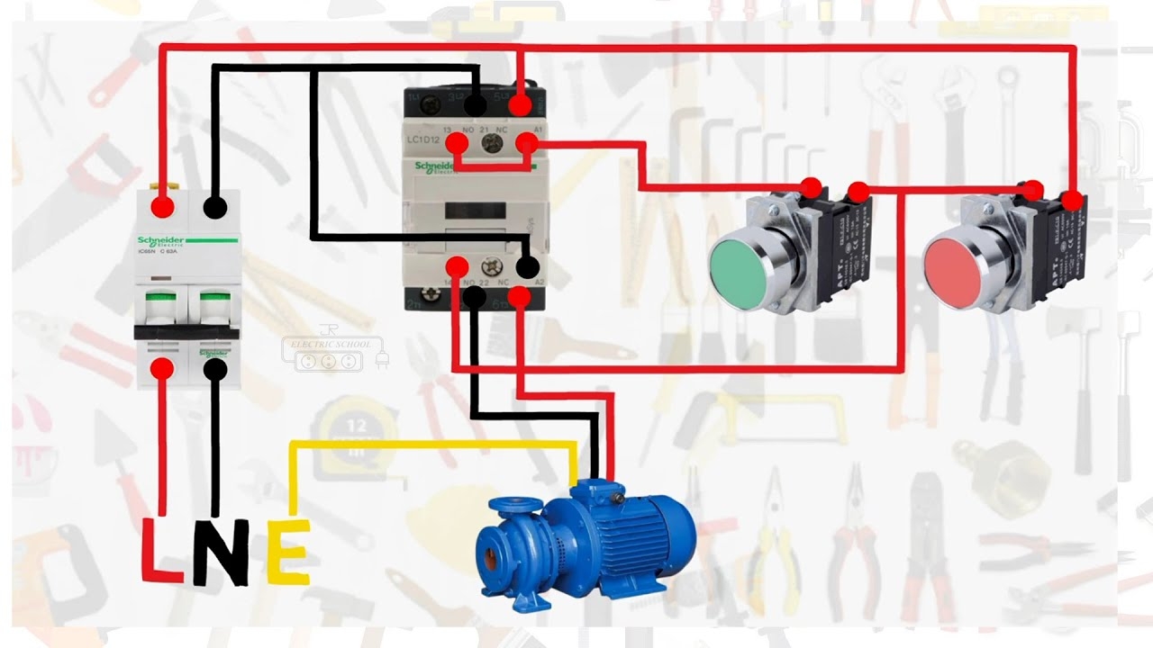
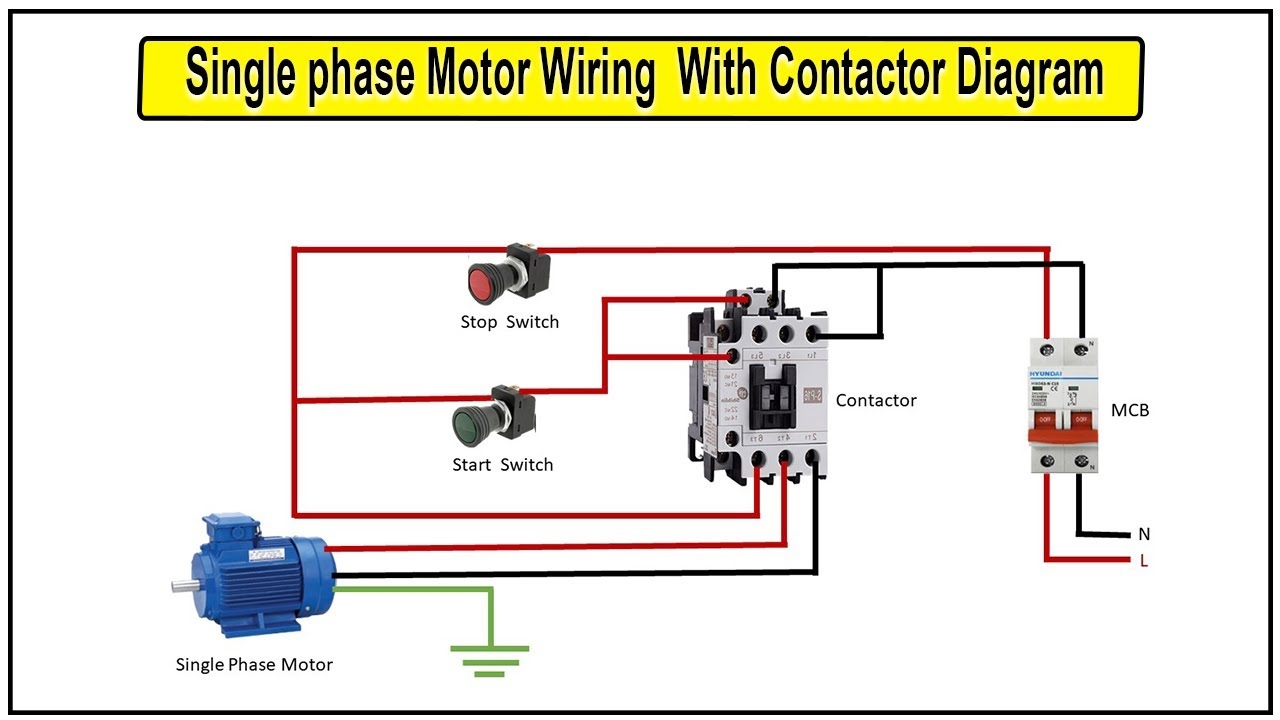
Single Phase Motor Connection With Magnetic Contactor Wiring Diagram YouTube
The image title is Single Phase Motor Connection With Magnetic Contactor Wiring Diagram YouTube, features dimensions of width 1280 px and height 720 px, with a file size of 1280 x 720 px. This image image/jpeg type visual are source from www.youtube.com.
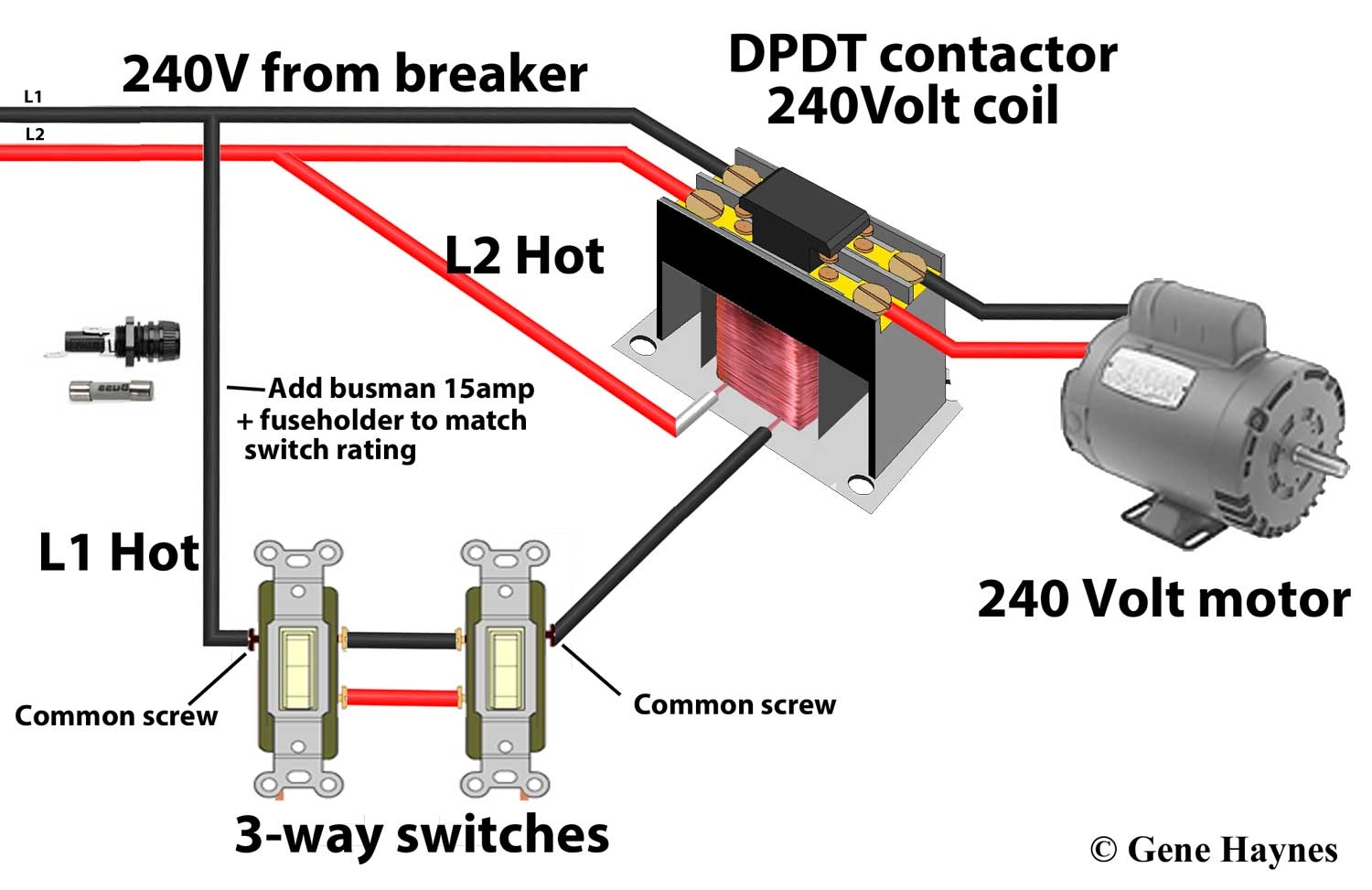
Contactors
The image title is Contactors, features dimensions of width 1500 px and height 973 px, with a file size of 1500 x 973 px. This image image/jpeg type visual are source from waterheatertimer.org.
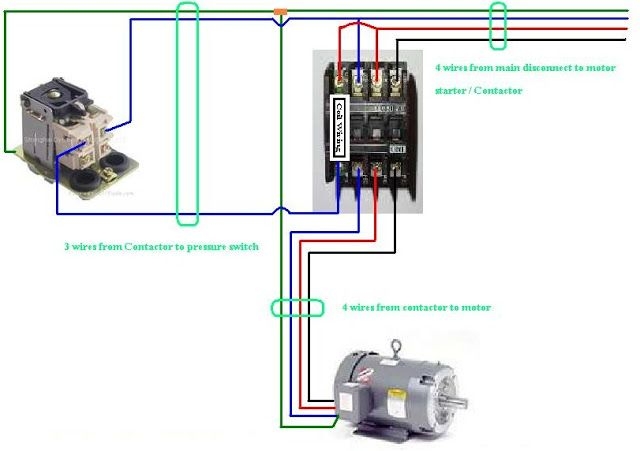
Three Phase Contactor Wiring Diagram Electrical Diagram Electrical Circuit Diagram Electrical Wiring Diagram
The image title is Three Phase Contactor Wiring Diagram Electrical Diagram Electrical Circuit Diagram Electrical Wiring Diagram, features dimensions of width 640 px and height 451 px, with a file size of 640 x 451. This image image/jpeg type visual are source from www.pinterest.com.
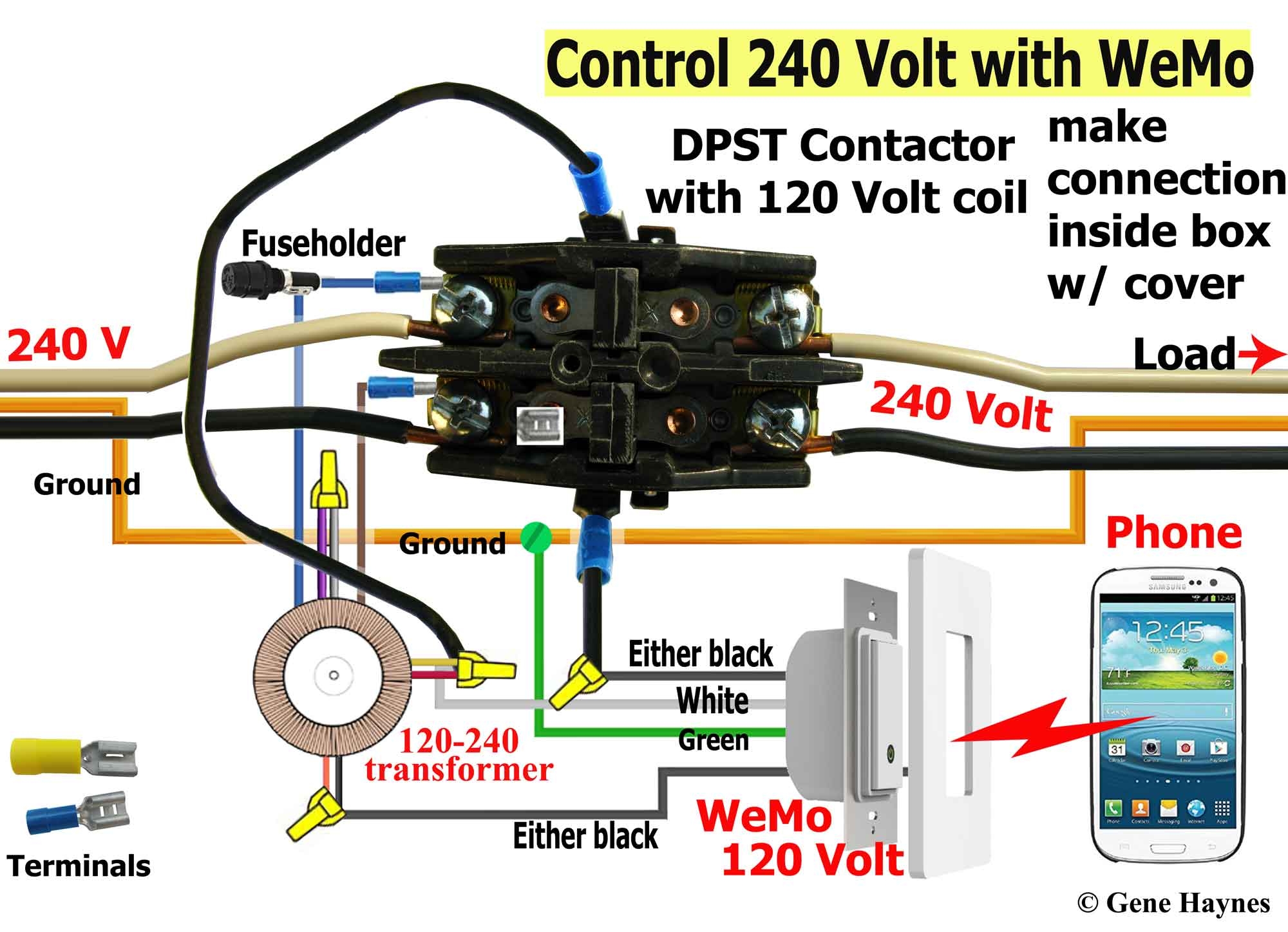
Control 240 Volt With WeMo
The image title is Control 240 Volt With WeMo, features dimensions of width 2000 px and height 1448 px, with a file size of 2000 x 1448. This image image/jpeg type visual are source from waterheatertimer.org.
How To Make Single Phase Motor Wiring With Contactor Diagram Motor YouTube
The image title is How To Make Single Phase Motor Wiring With Contactor Diagram Motor YouTube, features dimensions of width 1280 px and height 720 px, with a file size of 1280 x 720. This image image/jpeg type visual are source from www.youtube.com
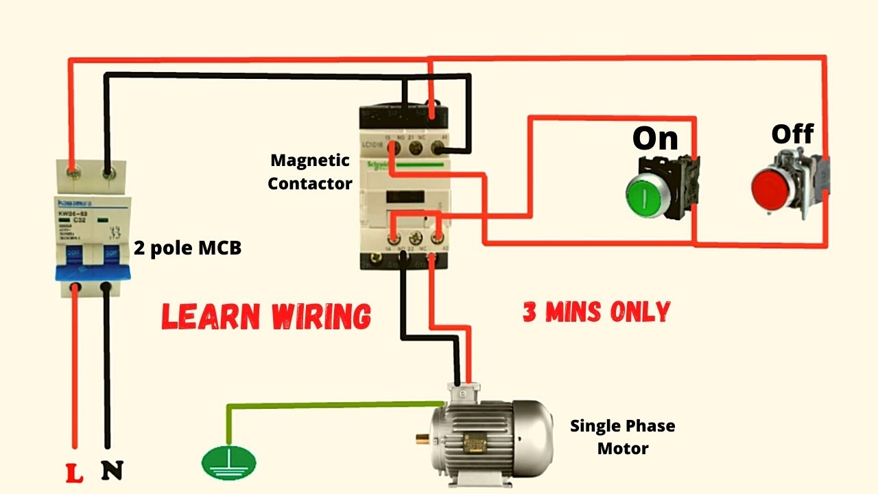
Single Phase Motor Connection With Magnetic Contactor Wiring Diagram YouTube
The image title is Single Phase Motor Connection With Magnetic Contactor Wiring Diagram YouTube, features dimensions of width 1280 px and height 720 px, with a file size of 1280 x 720. This image image/jpeg type visual are source from www.youtube.com.
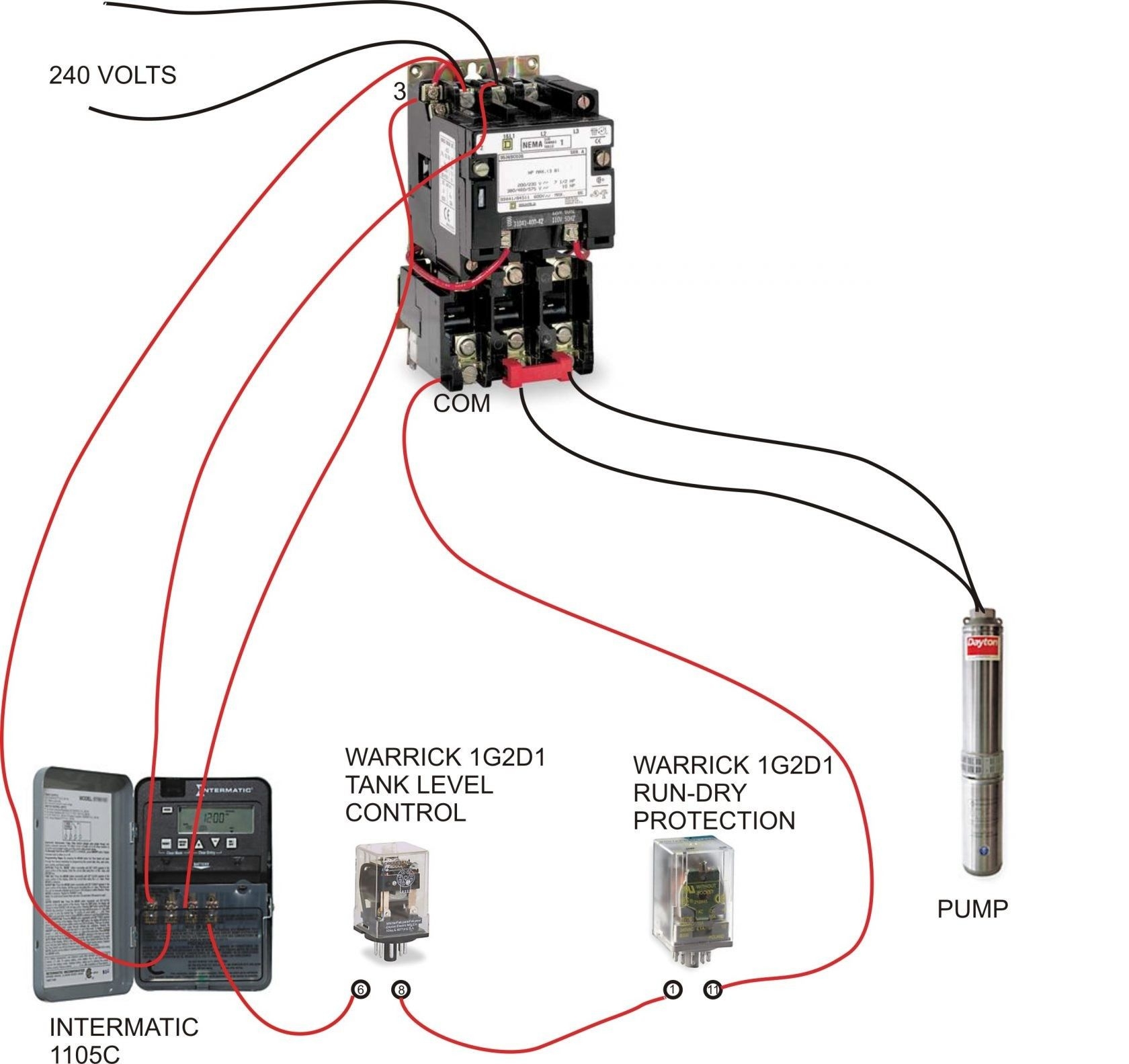
New Auxiliary Contactor Wiring Diagram Diagram Diagramtemplate Diagramsample Check More At Ht Electrical Circuit Diagram Electrical Wiring Diagram Well Pump
The image title is New Auxiliary Contactor Wiring Diagram Diagram Diagramtemplate Diagramsample Check More At Ht Electrical Circuit Diagram Electrical Wiring Diagram Well Pump, features dimensions of width 1680 px and height 1583 px, with a file size of 1680 x 1583. This image image/jpeg type visual are source from www.pinterest.com.
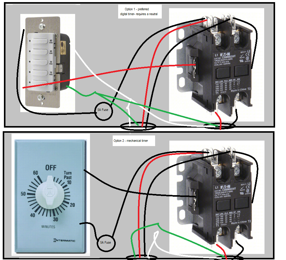
Electrical Using A Countdown Timer To Control A 40A 240V Contactor Home Improvement Stack Exchange
The image title is Electrical Using A Countdown Timer To Control A 40A 240V Contactor Home Improvement Stack Exchange, features dimensions of width 944 px and height 858 px, with a file size of 944 x 858.
The images on this page, sourced from Google for educational purposes, may be copyrighted. If you own an image and wish its removal or have copyright concerns, please contact us. We aim to promptly address these issues in compliance with our copyright policy and DMCA standards. Your cooperation is appreciated.
Related Keywords to 240 Volt Contactor Wiring Diagram:
240 volt coil contactor wiring diagram,240 volt contactor wiring diagram,how does a 240v contactor work,how to wire a 24v contactor,single phase 240 volt contactor wiring diagram
