Table of Contents
Exploring the Value of 2 Wire Crank Sensor Wiring Diagram
The Importance of Understanding 2 Wire Crank Sensor Wiring Diagram
In the world of automotive engineering, precision and accuracy are paramount. When it comes to the intricate network of sensors and wiring systems within a vehicle, having a comprehensive understanding of the 2 Wire Crank Sensor Wiring Diagram can make all the difference. This crucial diagram serves as a roadmap for technicians and enthusiasts alike, guiding them through the intricate process of connecting and troubleshooting the crank sensor. Let’s delve deeper into the value of this essential wiring diagram and explore the nuances that can enhance our knowledge of automotive technology.
Key Components of a 2 Wire Crank Sensor Wiring Diagram
The 2 Wire Crank Sensor Wiring Diagram typically consists of detailed schematics that outline the connections and configurations of the crank sensor within a vehicle. Understanding the key components of this diagram is essential for diagnosing issues and ensuring optimal performance. Some of the crucial elements that are often included in a 2 Wire Crank Sensor Wiring Diagram are:
Sensor Power Supply
Ground Connections
Signal Output
Connector Pinouts
Benefits of a Well-Designed Wiring Diagram
A well-designed 2 Wire Crank Sensor Wiring Diagram can offer a multitude of benefits for both seasoned professionals and novice enthusiasts. By following the detailed instructions and visual representations provided in the diagram, users can:
Efficiently troubleshoot sensor issues
Ensure proper sensor installation
Identify potential wiring faults
Optimize engine performance
Tips for Using a 2 Wire Crank Sensor Wiring Diagram
Navigating through a complex wiring diagram can be a daunting task, but with the right approach, users can make the most of this valuable resource. Here are some tips for effectively utilizing a 2 Wire Crank Sensor Wiring Diagram:
Refer to the manufacturer’s guidelines for accurate information
Use color-coded diagrams for easy identification of wires
Double-check connections before powering up the sensor
Seek professional help if unsure about any aspect of the wiring diagram
Conclusion
In conclusion, the 2 Wire Crank Sensor Wiring Diagram plays a pivotal role in the functioning and maintenance of modern vehicles. By grasping the intricacies of this diagram and leveraging its insights, automotive enthusiasts can enhance their understanding of sensor technology and improve their diagnostic capabilities. Whether you’re a seasoned mechanic or a curious hobbyist, exploring the value of the 2 Wire Crank Sensor Wiring Diagram can open up a world of possibilities in the realm of automotive engineering.
Related to 2 Wire Crank Sensor Wiring Diagram
- 2 Way Switch Wiring Diagram Pdf
- 2 Way Wiring Diagram For A Light Switch
- 2 Way Wiring Switch Diagram
- 2 Wire 220 Volt Wiring Diagram
- 2 Wire Alternator Wiring Diagram
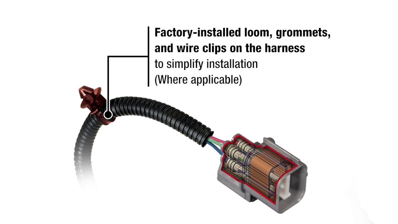
A Closer Look Crankshaft Position Sensors YouTube
The image title is A Closer Look Crankshaft Position Sensors YouTube, features dimensions of width 1280 px and height 720 px, with a file size of 1280 x 720 px. This image image/jpeg type visual are source from www.youtube.com.
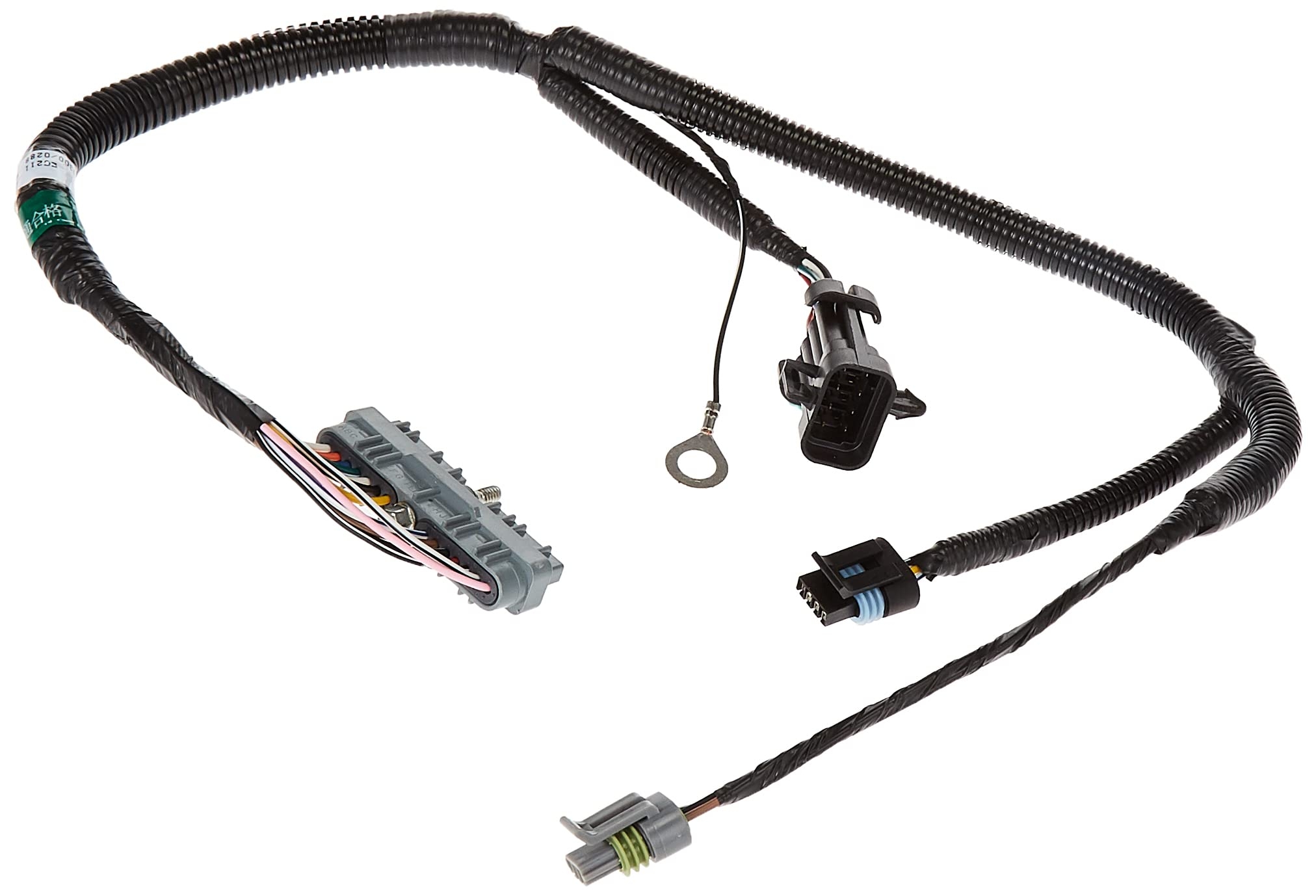
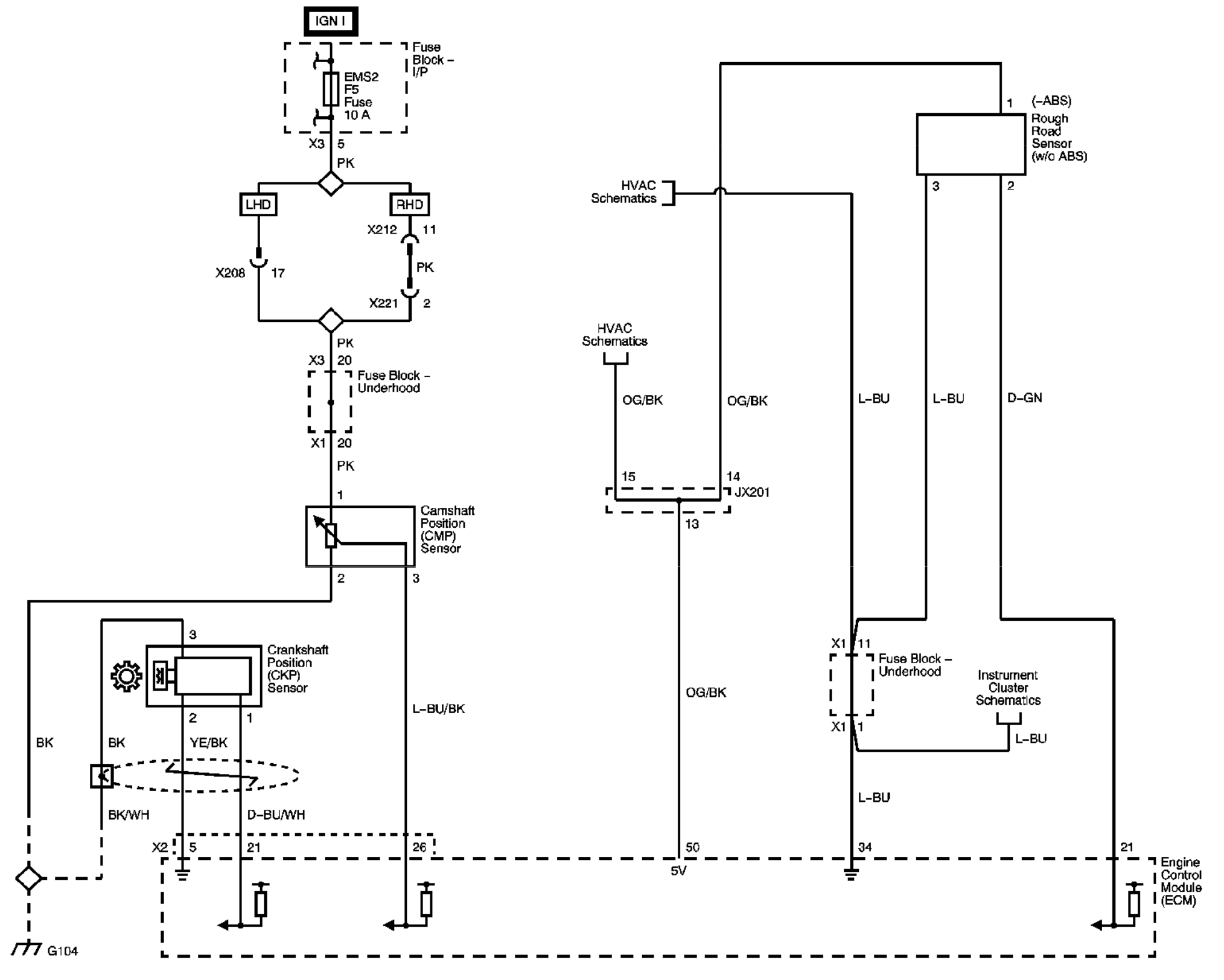
Amazon Dorman 645 688 Cam Crank And Ignition Harness Compatible With Select Models Automotive
The image title is Amazon Dorman 645 688 Cam Crank And Ignition Harness Compatible With Select Models Automotive, features dimensions of width 2024 px and height 1378 px, with a file size of 2024 x 1378 px. This image image/jpeg type visual are source from www.amazon.com.
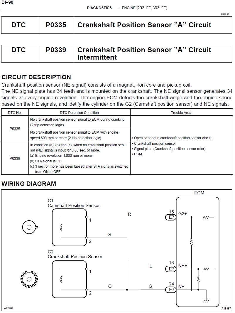
No Power To Cam Or Crank Sensor Help Please Page 3 Tacoma World
The image title is No Power To Cam Or Crank Sensor Help Please Page 3 Tacoma World, features dimensions of width 801 px and height 1066 px, with a file size of 801 x 1066. This image image/jpeg type visual are source from www.tacomaworld.com.
Wiring Advice Focus 1 6 TDCI 2011 Crankshaft Sensor Ford Focus Club Ford Owners Club Ford Forums
The image title is Wiring Advice Focus 1 6 TDCI 2011 Crankshaft Sensor Ford Focus Club Ford Owners Club Ford Forums, features dimensions of width 1232 px and height 765 px, with a file size of 1232 x 765. This image image/jpeg type visual are source from www.fordownersclub.com.
Automotive How To Wire Up Camshaft Position Sensor In Lab Environment Electrical Engineering Stack Exchange
The image title is Automotive How To Wire Up Camshaft Position Sensor In Lab Environment Electrical Engineering Stack Exchange, features dimensions of width 2028 px and height 1623 px, with a file size of 2028 x 1623. This image image/png type visual are source from electronics.stackexchange.com
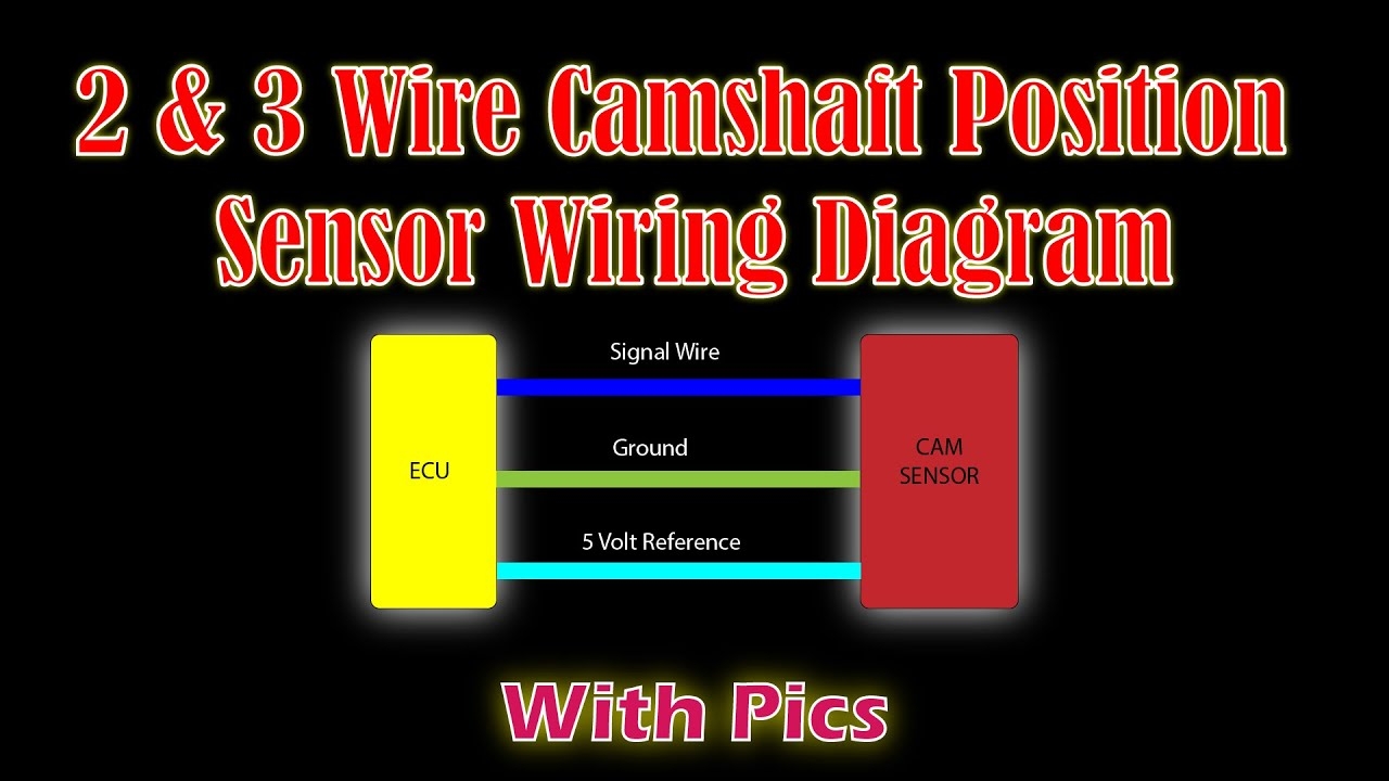
2 3 Wire Camshaft Position Wiring Diagram Easy Car Electrics YouTube
The image title is 2 3 Wire Camshaft Position Wiring Diagram Easy Car Electrics YouTube, features dimensions of width 1280 px and height 720 px, with a file size of 1280 x 720. This image image/jpeg type visual are source from www.youtube.com.
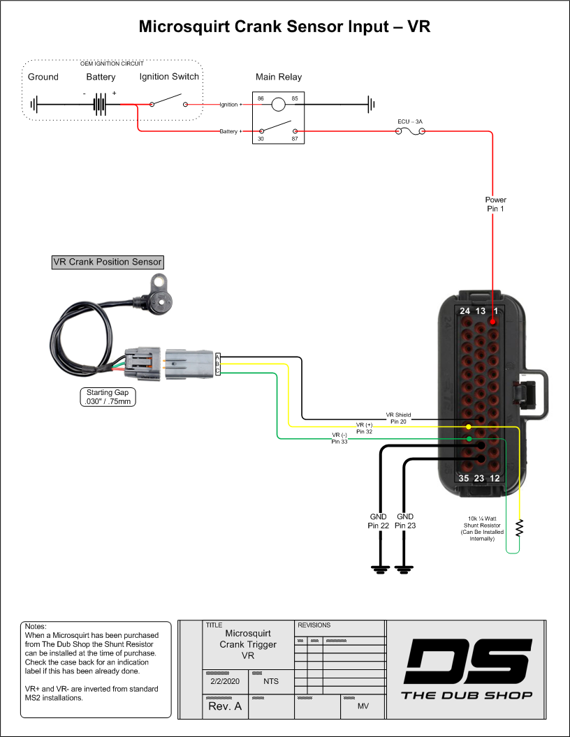
Microsquirt Wiring Diagrams
The image title is Microsquirt Wiring Diagrams, features dimensions of width 816 px and height 1056 px, with a file size of 816 x 1056. This image image/png type visual are source from thedubshop.com.
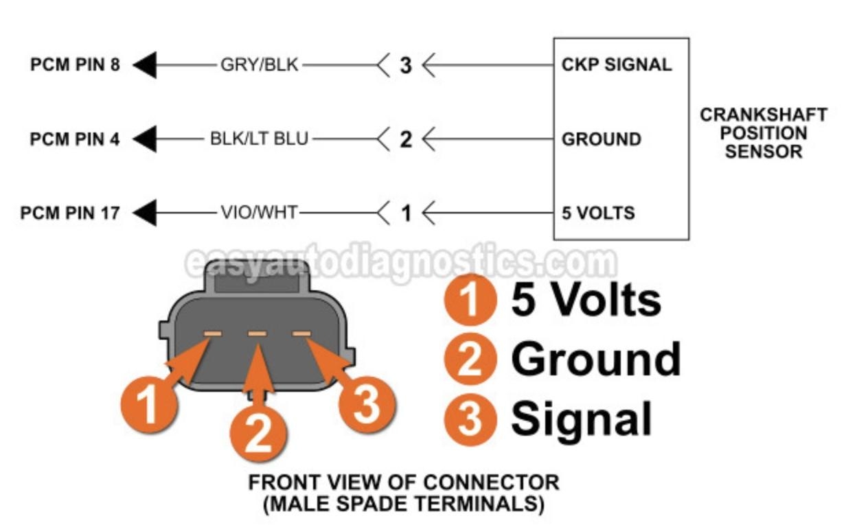
How To Test The Crankshaft Position Sensor 1994 2004 3 0L V6 Mitsubishi Montero Map Sensor Car Mechanic Automotive Mechanic
The image title is How To Test The Crankshaft Position Sensor 1994 2004 3 0L V6 Mitsubishi Montero Map Sensor Car Mechanic Automotive Mechanic, features dimensions of width 600 px and height 350 px, with a file size of 600 x 350.
The images on this page, sourced from Google for educational purposes, may be copyrighted. If you own an image and wish its removal or have copyright concerns, please contact us. We aim to promptly address these issues in compliance with our copyright policy and DMCA standards. Your cooperation is appreciated.
Related Keywords to 2 Wire Crank Sensor Wiring Diagram:
2 wire crank sensor wiring diagram,crankshaft position sensor wire colors,ford 2 wire crank sensor wiring diagram,how does a 2 wire crank sensor work,how does a 3 wire crank sensor work
