Table of Contents
Exploring the 6 Pin Accelerator Pedal Position Sensor Wiring Diagram
The Value of Understanding the 6 Pin Accelerator Pedal Position Sensor Wiring Diagram
The 6 Pin Accelerator Pedal Position Sensor Wiring Diagram is a crucial component for anyone looking to delve into the intricate workings of their vehicle’s acceleration system. By deciphering this diagram, you gain valuable insights into how the sensor communicates with the engine control unit, ultimately influencing the vehicle’s performance and responsiveness. In this comprehensive guide, we will break down the essential aspects of the 6 Pin Accelerator Pedal Position Sensor Wiring Diagram, offering valuable information and practical tips to enhance your understanding.
Overview of the 6 Pin Accelerator Pedal Position Sensor
Before delving into the wiring diagram, it is essential to grasp the function of the 6 Pin Accelerator Pedal Position Sensor. This sensor is responsible for relaying the position of the accelerator pedal to the engine control unit, allowing for precise control of the throttle opening and fuel delivery. Understanding how this sensor operates is fundamental to comprehending its wiring diagram effectively.
Key Components of the Wiring Diagram
The 6 Pin Accelerator Pedal Position Sensor Wiring Diagram typically consists of various components that play a crucial role in the sensor’s functionality. These components include the power supply, ground connection, signal wire, reference voltage, and more. Each element is interconnected in a specific way to ensure seamless communication between the sensor and the engine control unit.
Interpreting the Wiring Diagram
Interpreting the 6 Pin Accelerator Pedal Position Sensor Wiring Diagram may seem daunting at first, but with a systematic approach, you can unravel its complexities. By understanding the purpose of each wire and connection within the diagram, you can troubleshoot potential issues, conduct maintenance tasks, or even modify the sensor’s configuration to optimize performance.
Steps to Analyze the Wiring Diagram
Identify each wire’s function based on color coding or labeling.
Trace the path of the wires to determine how they are interconnected within the system.
Consult the vehicle’s service manual for detailed information on the sensor’s wiring diagram.
Use a multimeter to test the continuity and voltage of each wire for accuracy.
Practical Applications of the Wiring Diagram
Once you have a firm grasp of the 6 Pin Accelerator Pedal Position Sensor Wiring Diagram, you can leverage this knowledge in various ways. Whether you are troubleshooting a faulty sensor, upgrading your vehicle’s performance, or conducting routine maintenance, understanding the wiring diagram is indispensable for achieving optimal results.
Tips for Harnessing the Wiring Diagram’s Potential
Document any modifications or repairs made to the sensor’s wiring for future reference.
Regularly inspect the wiring harness for signs of wear or damage that may affect sensor performance.
Consult with a professional mechanic or technician for complex wiring issues that require specialized expertise.
Related to 6 Pin Accelerator Pedal Position Sensor Wiring Diagram
- 50s Les Paul Wiring Diagram
- 50s Wiring Les Paul Diagram
- 568b Wiring Diagram
- 6 4 Ohm Speaker Wiring Diagram
- 6 Lead Motor Wiring Diagram
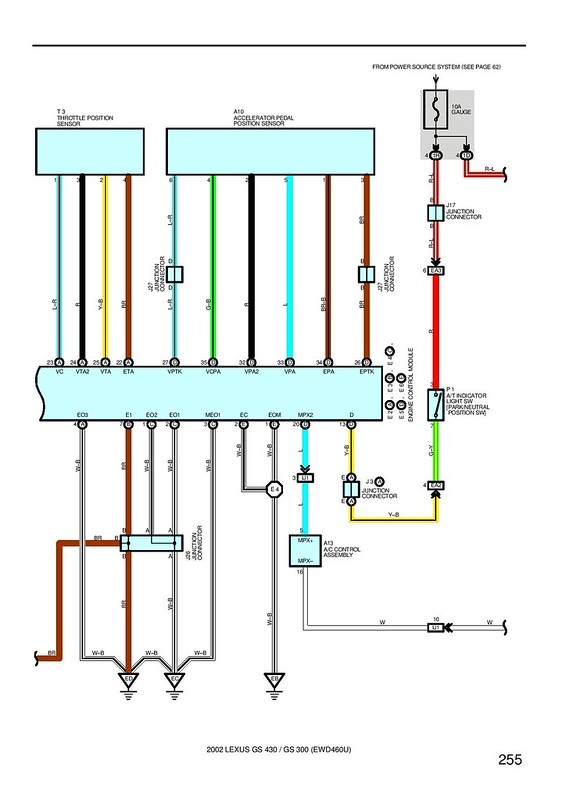
DBW With Stock Intake Manifold Page 2 Supra Forums
The image title is DBW With Stock Intake Manifold Page 2 Supra Forums, features dimensions of width 566 px and height 800 px, with a file size of 566 x 800 px. This image image/jpeg type visual are source from www.supraforums.com.
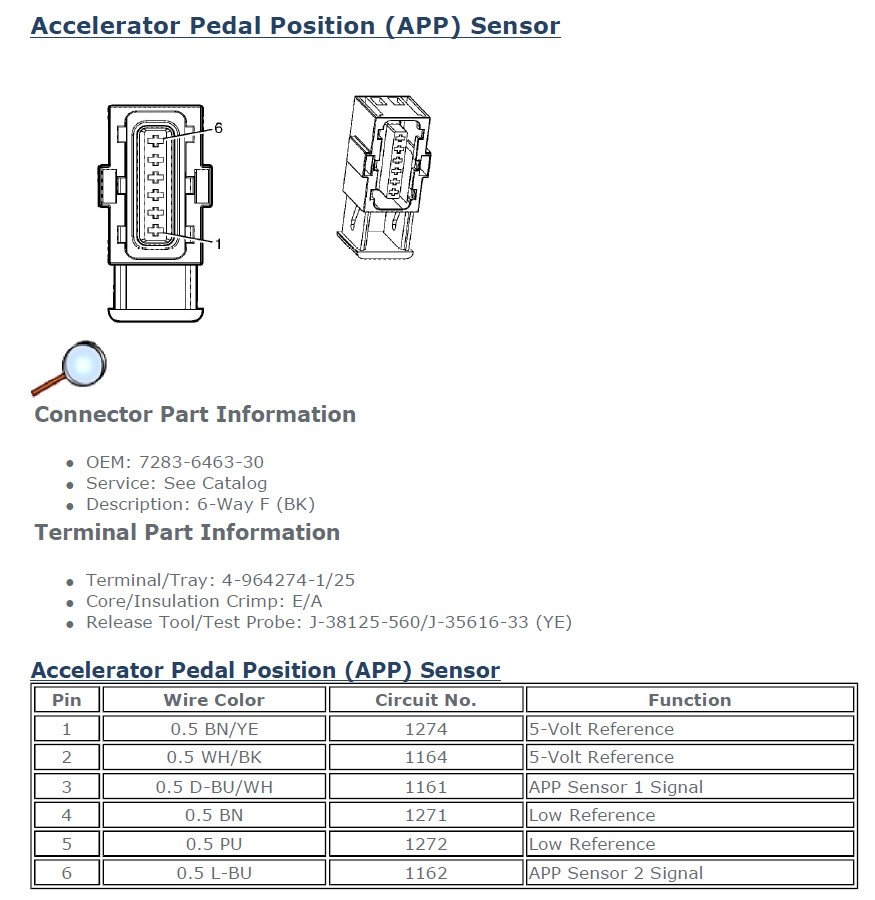
MX5 GTX DBW Ethrottle Module Wiring G4 Forums Link Engine Management
The image title is MX5 GTX DBW Ethrottle Module Wiring G4 Forums Link Engine Management, features dimensions of width 875 px and height 900 px, with a file size of 875 x 900 px. This image image/jpeg type visual are source from forums.linkecu.com.
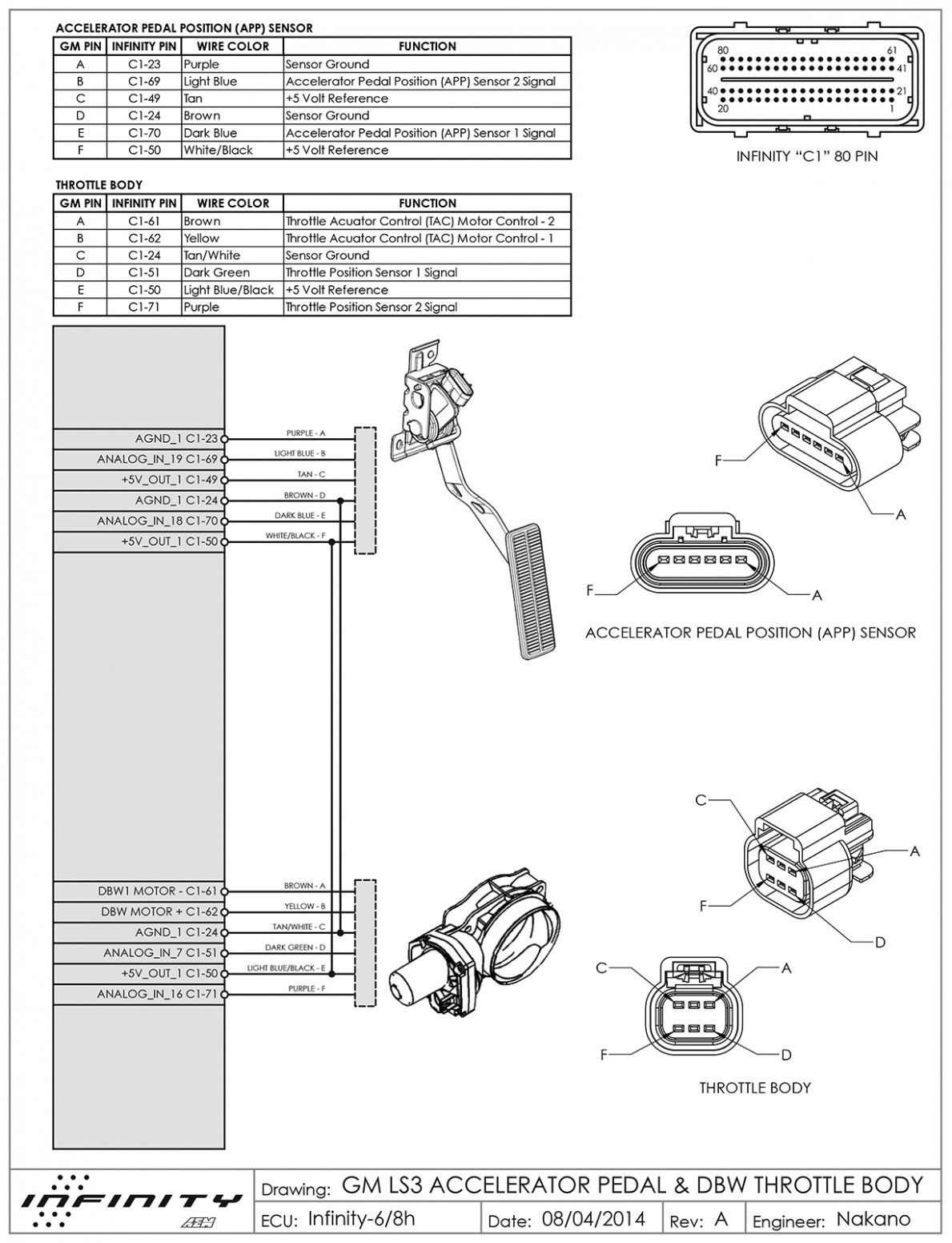
Engine Diagram Vq8de Yamaha Car Throttle Throttle Diagram
The image title is Engine Diagram Vq8de Yamaha Car Throttle Throttle Diagram, features dimensions of width 1189 px and height 1552 px, with a file size of 1189 x 1552. This image image/jpeg type visual are source from www.pinterest.com.
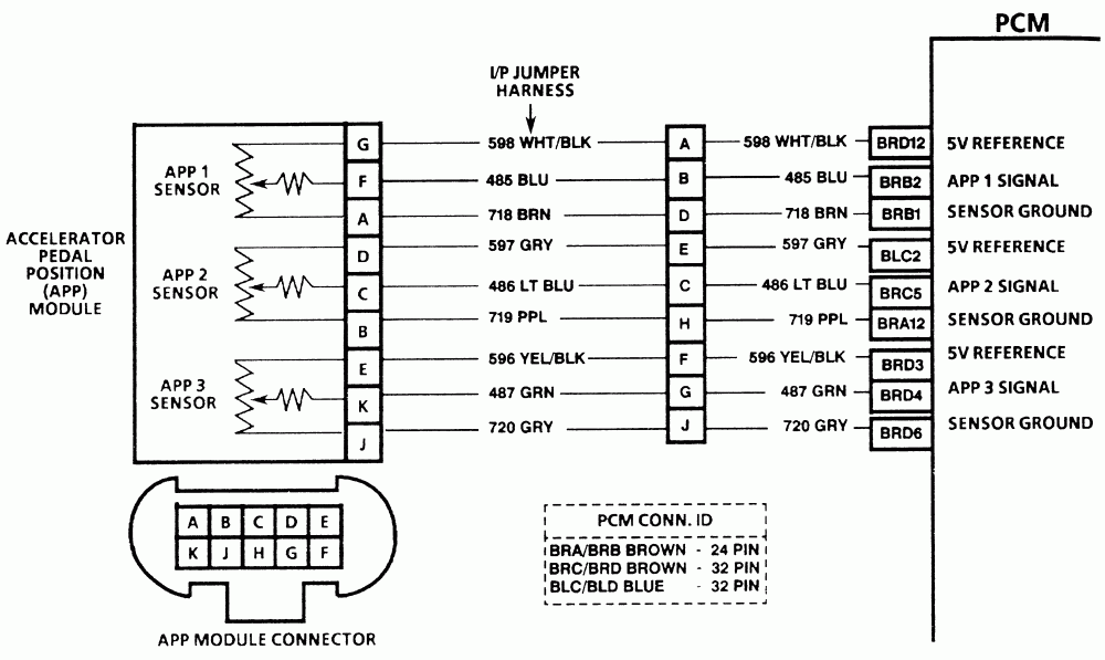
Drive By Wire Accelerator Nonfunctional LS1TECH Camaro And Firebird Forum Discussion
The image title is Drive By Wire Accelerator Nonfunctional LS1TECH Camaro And Firebird Forum Discussion, features dimensions of width 1000 px and height 597 px, with a file size of 1000 x 597. This image image/gif type visual are source from ls1tech.com.
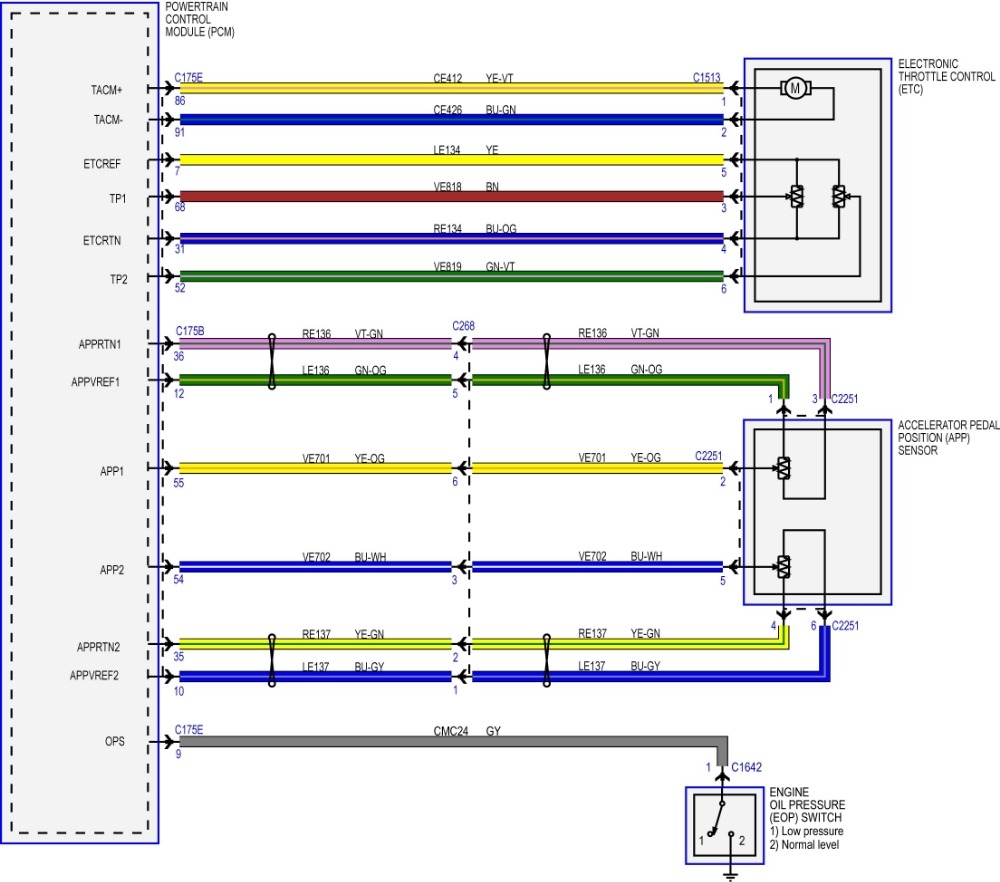
2015 F 150 Acceleration Pedal Position Wiring Diagram Request And Throttle Wir ScannerDanner Forum SCANNERDANNER
The image title is 2015 F 150 Acceleration Pedal Position Wiring Diagram Request And Throttle Wir ScannerDanner Forum SCANNERDANNER, features dimensions of width 1000 px and height 882 px, with a file size of 1000 x 882. This image image/jpeg type visual are source from www.scannerdanner.com
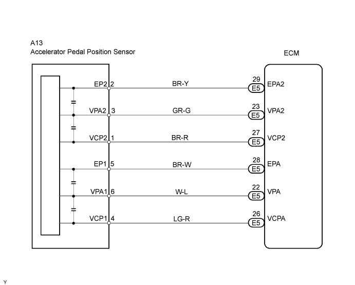
GSIC Global Service Information Center
The image title is GSIC Global Service Information Center, features dimensions of width 691 px and height 555 px, with a file size of 691 x 555. This image image/png type visual are source from skcmspvtltd.org.
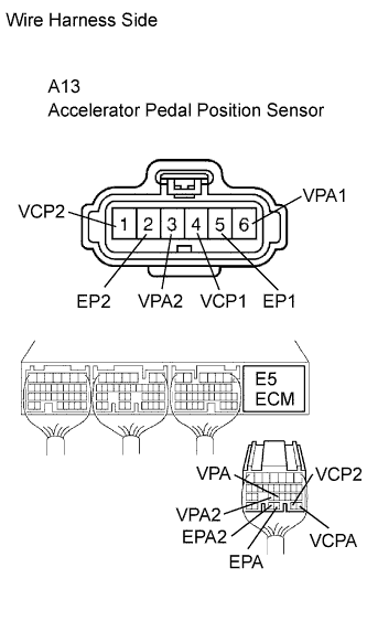
GSIC Global Service Information Center
The image title is GSIC Global Service Information Center, features dimensions of width 333 px and height 573 px, with a file size of 333 x 573. This image image/png type visual are source from skcmspvtltd.org.
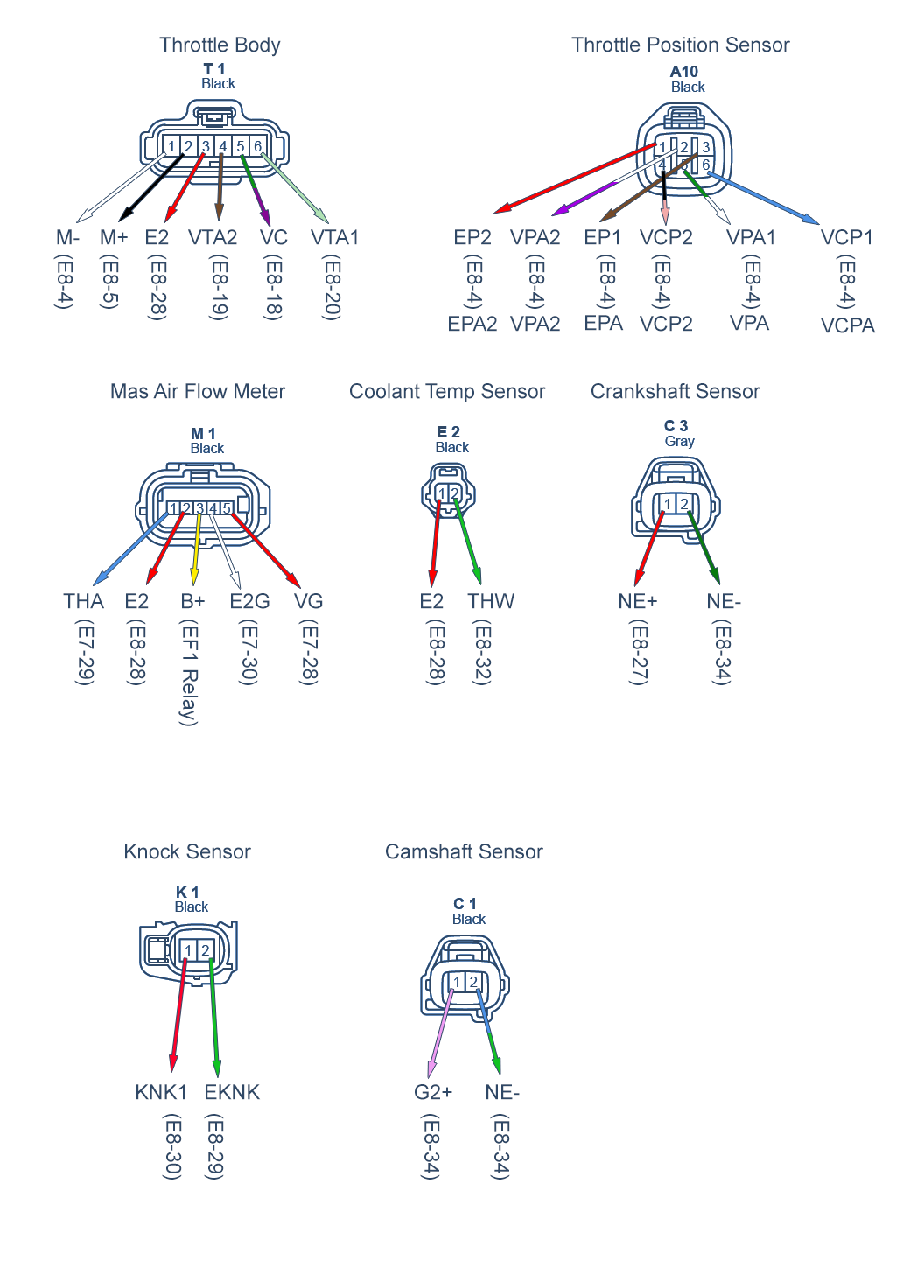
Toyota TPS And APS Wiring Diagram G4x Forums Link Engine Management
The image title is Toyota TPS And APS Wiring Diagram G4x Forums Link Engine Management, features dimensions of width 1056 px and height 1472 px, with a file size of 1056 x 1472.
The images on this page, sourced from Google for educational purposes, may be copyrighted. If you own an image and wish its removal or have copyright concerns, please contact us. We aim to promptly address these issues in compliance with our copyright policy and DMCA standards. Your cooperation is appreciated.
Related Keywords to 6 Pin Accelerator Pedal Position Sensor Wiring Diagram:
6 pin accelerator pedal position sensor wiring diagram,6 pin throttle position sensor wiring diagram,nissan 6 pin throttle position sensor wiring diagram,toyota 6 pin accelerator pedal position sensor wiring diagram,toyota 6 pin throttle position sensor wiring diagram
