Table of Contents
Exploring the 4 Wire Proximity Sensor Wiring Diagram
The Value of 4 Wire Proximity Sensor Wiring Diagram
When it comes to industrial automation and control systems, having a clear understanding of the wiring diagrams is crucial for efficient operation. One such essential component is the 4 wire proximity sensor, which plays a vital role in detecting the presence of objects without physical contact. Understanding the intricacies of the 4 wire proximity sensor wiring diagram is paramount for ensuring optimal performance and reliability in various applications.
Understanding the Basics of 4 Wire Proximity Sensors
Before delving into the wiring diagram, it’s important to grasp the basic functioning of a 4 wire proximity sensor. These sensors use electromagnetic fields to detect the presence or absence of an object within their sensing range. They are commonly used in industrial settings to monitor production processes, track inventory, and ensure safety by detecting obstructions or malfunctions. The 4 wire configuration consists of two wires for power supply and two wires for signal output, allowing for precise and reliable detection capabilities.
Components of a 4 Wire Proximity Sensor Wiring Diagram
A typical 4 wire proximity sensor wiring diagram includes various components such as power supply connections, signal output connections, ground connections, and load connections. Each component plays a crucial role in ensuring the sensor operates effectively and communicates seamlessly with the control system. Understanding how these components interact and are wired together is essential for troubleshooting issues and maintaining optimal performance.
Steps to Wire a 4 Wire Proximity Sensor
Identify the power supply terminals on the sensor and connect the positive and negative wires accordingly.
Locate the signal output terminals and connect them to the input terminals of the control system.
Connect the ground wire to the designated ground terminal to ensure proper grounding and prevent electrical interference.
If the sensor is used to control a load, connect the load wires to the output terminals of the sensor for activating the load based on the sensor’s detection.
Tips for Troubleshooting 4 Wire Proximity Sensor Wiring
Check the power supply connections to ensure the sensor is receiving adequate voltage.
Verify the signal output connections to the control system are secure and properly aligned.
Inspect the ground connection for any loose or damaged wires that may affect the sensor’s performance.
If the sensor is not detecting objects accurately, recalibrate the sensing range and sensitivity settings.
In conclusion, mastering the 4 wire proximity sensor wiring diagram is essential for anyone working with industrial automation systems. By understanding the components, connections, and troubleshooting tips outlined in this article, you can ensure the seamless operation of these sensors in various applications. Remember to follow best practices and safety guidelines when working with electrical components to prevent accidents and ensure efficiency in your operations.
Related to 4 Wire Proximity Sensor Wiring Diagram
- 4 Wire O2 Sensor Wiring Diagram
- 4 Wire O2 Sensor Wiring Diagram Honda
- 4 Wire O2 Sensor Wiring Diagram Nissan
- 4 Wire Oxygen Sensor Wiring Diagram
- 4 Wire Phone Jack Wiring Diagram
3 Wire PNP NPN Sensor Wiring Sensor Connection Diagram ElectricalTechnician YouTube
The image title is 3 Wire PNP NPN Sensor Wiring Sensor Connection Diagram ElectricalTechnician YouTube, features dimensions of width 1280 px and height 720 px, with a file size of 1280 x 720 px. This image image/jpeg type visual are source from www.youtube.com.
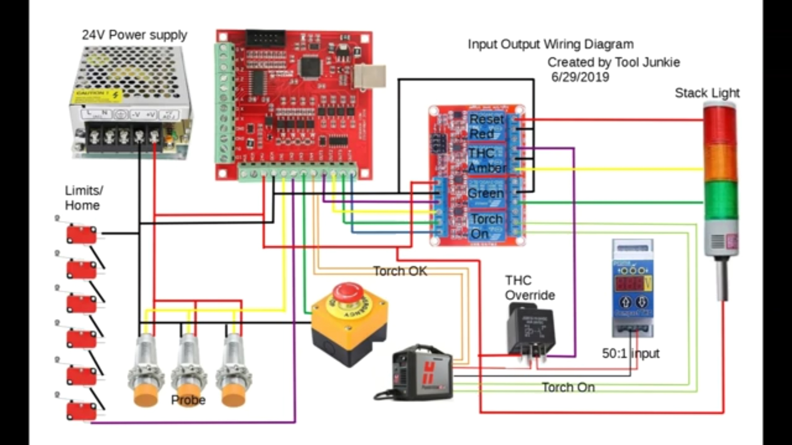
Proximity Sensor Wiring Langmuir Systems Forum
The image title is Proximity Sensor Wiring Langmuir Systems Forum, features dimensions of width 2560 px and height 1440 px, with a file size of 2560 x 1440 px. This image image/jpeg type visual are source from forum.langmuirsystems.com.
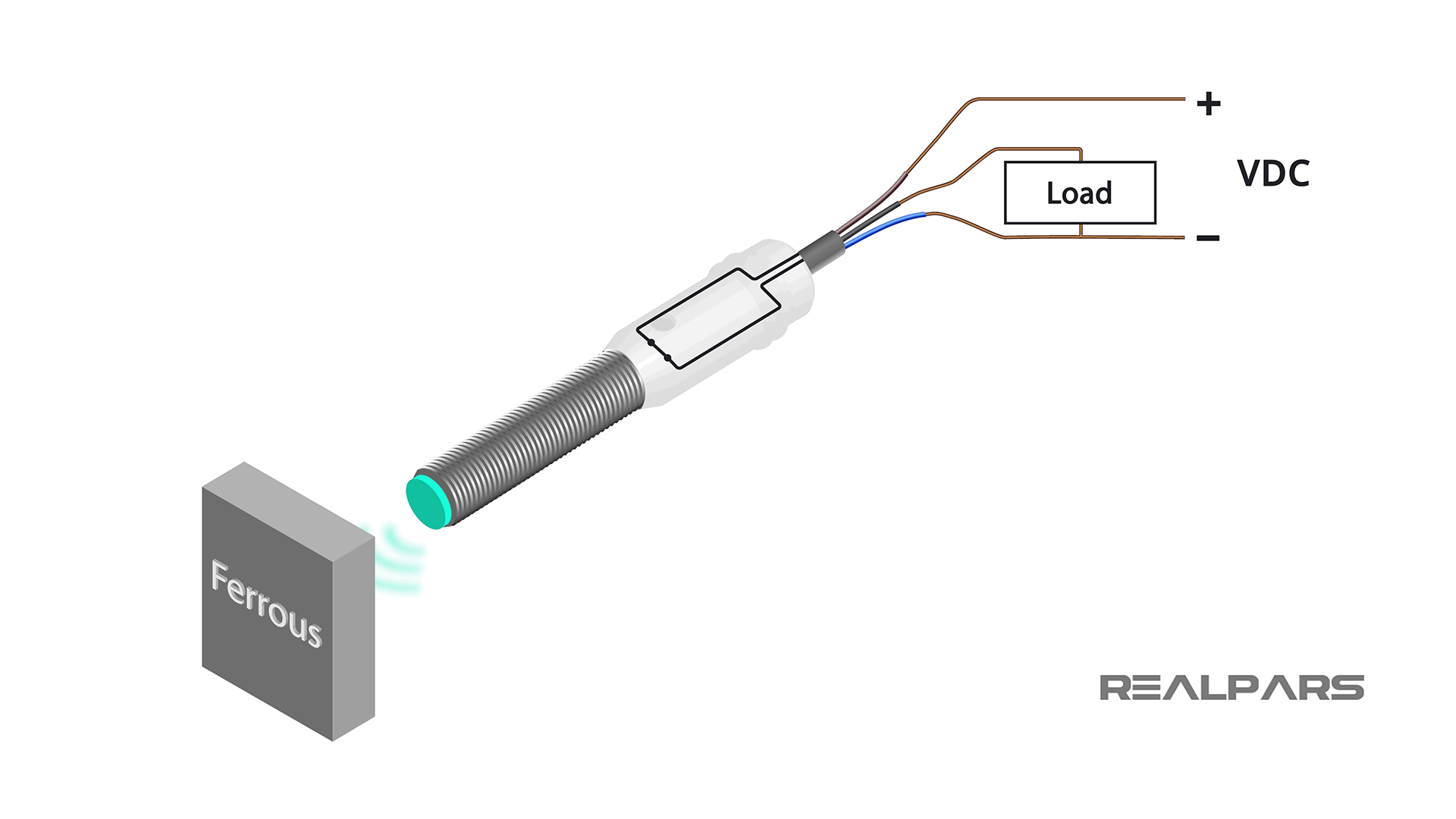
3 Wire Inductive Proximity Sensor How To Read The Datasheet RealPars
The image title is 3 Wire Inductive Proximity Sensor How To Read The Datasheet RealPars, features dimensions of width 1920 px and height 1080 px, with a file size of 1920 x 1080. This image image/png type visual are source from www.realpars.com.
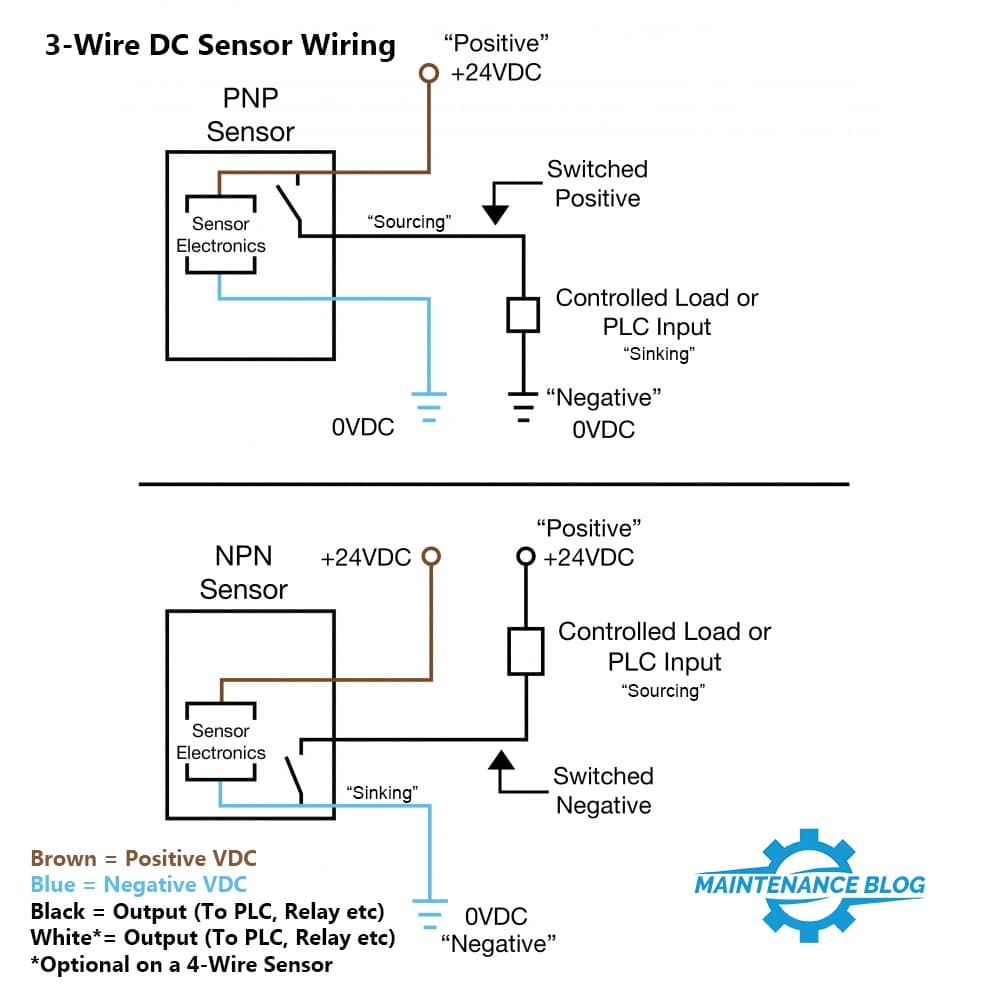
PNP Vs NPN Sensor Wiring Basics Part 1 Maintenance Blog
The image title is PNP Vs NPN Sensor Wiring Basics Part 1 Maintenance Blog, features dimensions of width 1000 px and height 1000 px, with a file size of 1000 x 1000. This image image/jpeg type visual are source from maintenanceblog.com.
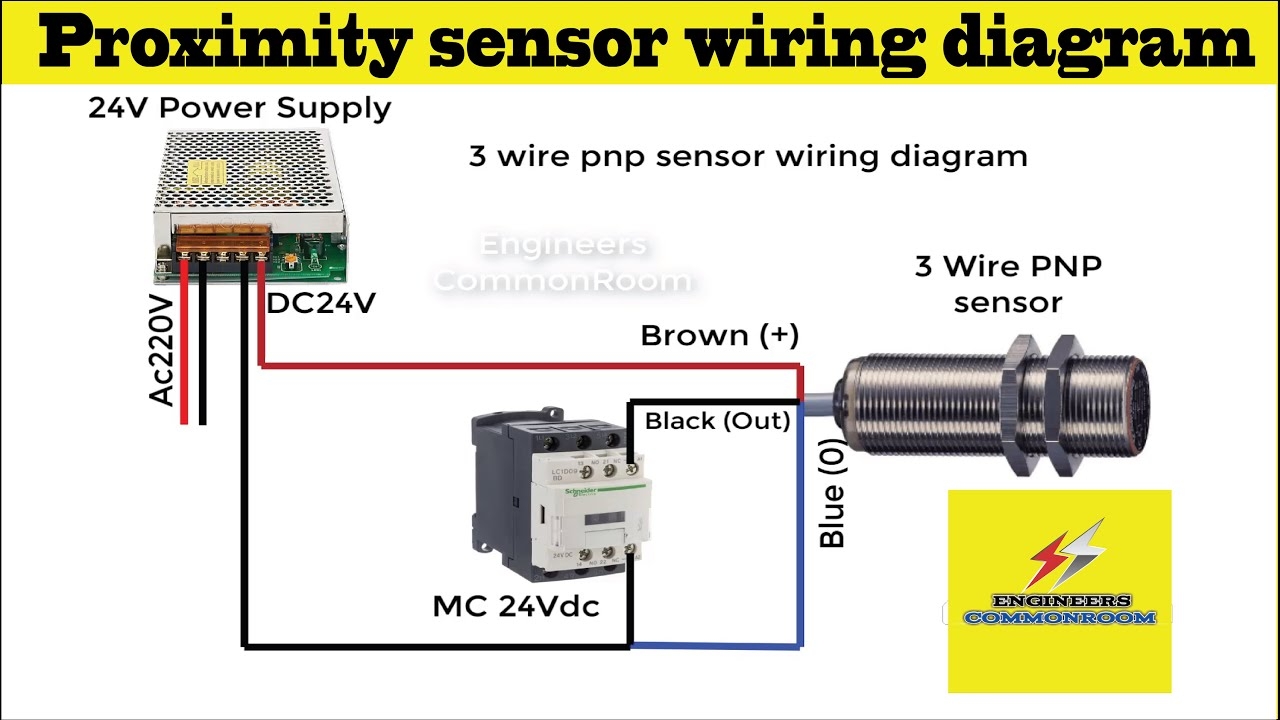
3 Wire Proximity Sensor Wiring Diagram Engineers CommonRoom Electrical Circuit Diagram YouTube
The image title is 3 Wire Proximity Sensor Wiring Diagram Engineers CommonRoom Electrical Circuit Diagram YouTube, features dimensions of width 1280 px and height 720 px, with a file size of 1280 x 720. This image image/jpeg type visual are source from www.youtube.com
Capacitive Sensors Power Source Four Wire Sensors
The image title is Capacitive Sensors Power Source Four Wire Sensors, features dimensions of width 717 px and height 300 px, with a file size of 717 x 300. This image image/jpeg type visual are source from www.pepperl-fuchs.com.
Connecting Sensor Ouput With More Than 5v To Input Pin Arduino Yun General Electronics Arduino Forum
The image title is Connecting Sensor Ouput With More Than 5v To Input Pin Arduino Yun General Electronics Arduino Forum, features dimensions of width 2560 px and height 1920 px, with a file size of 4608 x 3456. This image image/jpeg type visual are source from forum.arduino.cc.
Proximity Sensor Wiring Diagram And Connection Procedure Electrical Circuit Diagram Electrical Wiring Diagram Electronic Circuit Design
The image title is Proximity Sensor Wiring Diagram And Connection Procedure Electrical Circuit Diagram Electrical Wiring Diagram Electronic Circuit Design, features dimensions of width 1952 px and height 1624 px, with a file size of 1952 x 1624.
The images on this page, sourced from Google for educational purposes, may be copyrighted. If you own an image and wish its removal or have copyright concerns, please contact us. We aim to promptly address these issues in compliance with our copyright policy and DMCA standards. Your cooperation is appreciated.
Related Keywords to 4 Wire Proximity Sensor Wiring Diagram:
4 wire proximity sensor wire color code,4 wire proximity sensor wiring diagram,4-wire proximity switch wiring diagram,difference between 3 wire and 4 wire proximity sensor,how to wire a 4 wire proximity sensor


