Table of Contents
Exploring the 4 Wire O2 Sensor Wiring Diagram
Exploring the 4 Wire O2 Sensor Wiring Diagram
Understanding the intricacies of automotive sensors is crucial for any car enthusiast or DIY mechanic. Among these sensors, the 4 wire O2 sensor plays a pivotal role in optimizing engine performance and fuel efficiency. Delving into the world of wiring diagrams for this sensor can provide valuable insights into troubleshooting, maintenance, and upgrades for your vehicle. Let’s unravel the mysteries of the 4 wire O2 sensor wiring diagram and explore its significance in modern automotive technology.
The Basics of 4 Wire O2 Sensor Wiring Diagram
The 4 wire O2 sensor is a vital component of the engine management system, responsible for monitoring the oxygen levels in the exhaust gases. This information is essential for adjusting the air-fuel mixture to maintain optimal combustion efficiency. Understanding the wiring diagram of the 4 wire O2 sensor is crucial for connecting it correctly to the vehicle’s electrical system.
Components of the 4 Wire O2 Sensor Wiring Diagram
The wiring diagram for a 4 wire O2 sensor typically includes the sensor itself, the harness connector, and the vehicle’s ECU (Engine Control Unit). Each wire in the diagram serves a specific function, such as providing power, ground, signal output, and heater control. Properly identifying these components and their corresponding connections is essential for ensuring the sensor operates effectively.
Interpreting the Wiring Colors
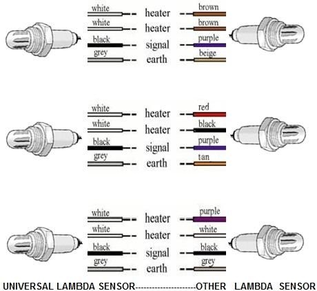
In the 4 wire O2 sensor wiring diagram, the colors of the wires can vary depending on the manufacturer and model of the sensor. While the standard color-coding convention is black for ground, white for signal output, gray for heater control, and purple for power, it’s essential to refer to the specific wiring diagram provided by the sensor manufacturer for accurate connections.
Installation and Troubleshooting Tips
Ensure proper insulation of the wires to prevent shorts or electrical malfunctions.
Use a multimeter to test the continuity and voltage of each wire in the sensor circuit.
Check for any corrosion or damage in the sensor connector that may affect the signal transmission.
Refer to the vehicle’s service manual for the exact wiring diagram and diagnostic procedures for the 4 wire O2 sensor.
Upgrading to a Wideband O2 Sensor
For advanced tuning and precision in air-fuel ratio control, many enthusiasts opt to upgrade to a wideband O2 sensor. The wiring diagram for a wideband sensor may differ from that of a standard 4 wire O2 sensor, requiring additional connections for the wideband controller. Understanding the wiring layout and compatibility with the vehicle’s ECU is crucial for a successful upgrade.
Benefits of Wideband O2 Sensor
Enhanced accuracy in monitoring the air-fuel ratio for performance tuning.
Greater flexibility in adjusting fuel delivery and ignition timing for optimized engine performance.
Improved fuel efficiency and reduced emissions compliance for environmentally conscious driving.
Conclusion
In conclusion, delving into the 4 wire O2 sensor wiring diagram can provide valuable insights into your vehicle’s engine management system. By understanding the components, connections, and color codes of the wiring diagram, you can ensure proper installation, troubleshooting, and even upgrades to enhance your vehicle’s performance. Whether you’re a seasoned mechanic or a novice enthusiast, exploring the intricacies of sensor wiring diagrams opens up a world of possibilities for maximizing your driving experience.
Related to 4 Wire O2 Sensor Wiring Diagram
- 4 Wire Lambda Sensor Wiring Diagram
- 4 Wire Led Light Wiring Diagram
- 4 Wire Light Fixture Wiring Diagram
- 4 Wire Mobile Home Wiring Diagram
- 4 Wire Motor Wiring Diagram
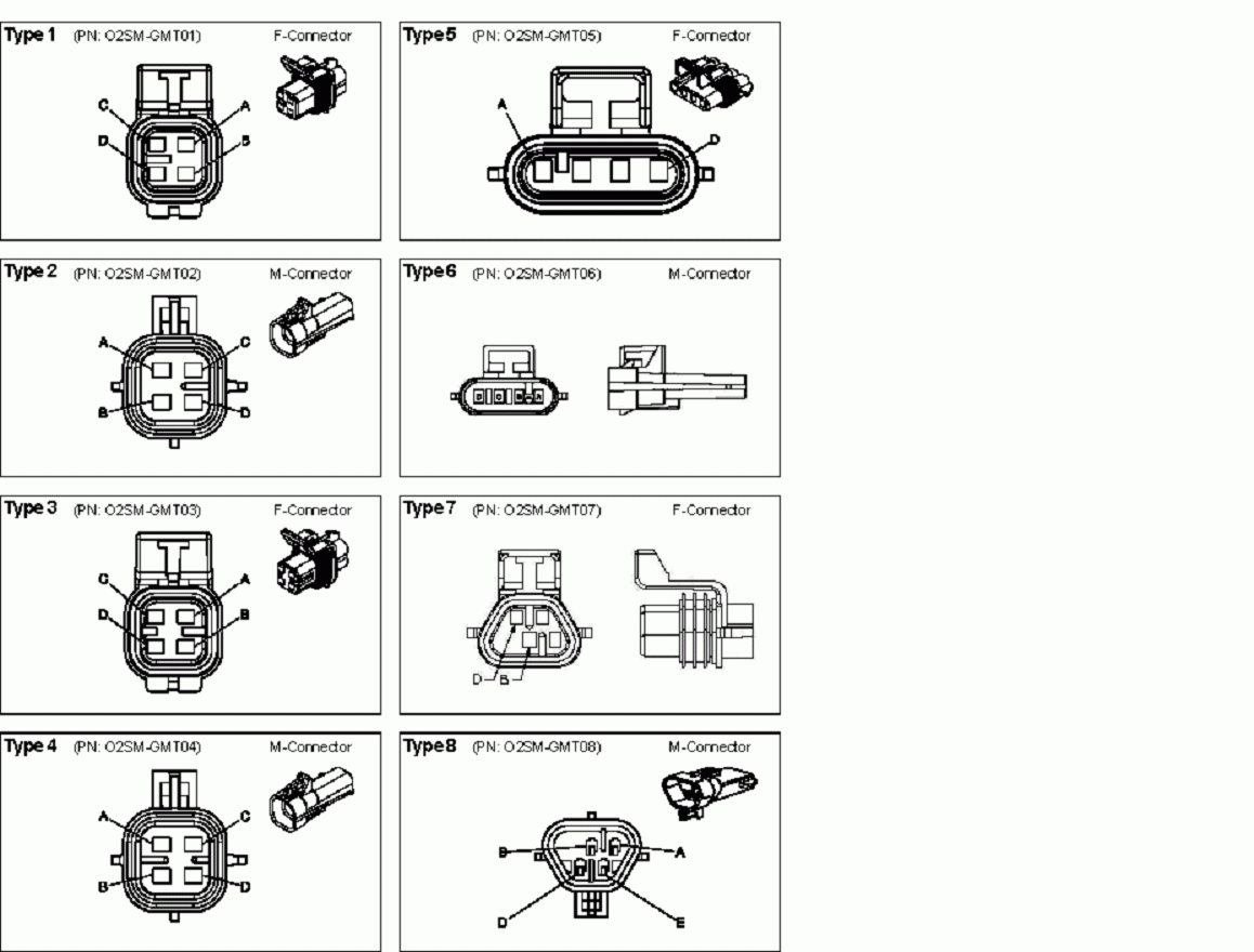
O2 Simulator Tester GM 4 Wire General Motors 1996 2003
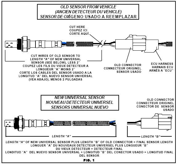
The image title is O2 Simulator Tester GM 4 Wire General Motors 1996 2003, features dimensions of width 1158 px and height 880 px, with a file size of 1158 x 880 px. This image image/gif type visual are source from www.afterthoughtsauto.com.
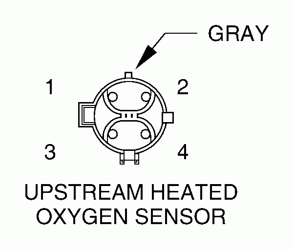
4 Wire Oxygen Sensor Color Codes Functions Wiring Diagrams
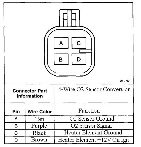
The image title is 4 Wire Oxygen Sensor Color Codes Functions Wiring Diagrams, features dimensions of width 602 px and height 512 px, with a file size of 602 x 512 px. This image image/gif type visual are source from www.justanswer.com.
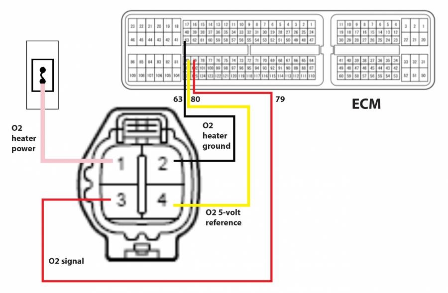
Does An Upstream O2 Sensor Have A Fuse 01 T C 3 8 Moparts Forums
The image title is Does An Upstream O2 Sensor Have A Fuse 01 T C 3 8 Moparts Forums, features dimensions of width 900 px and height 589 px, with a file size of 900 x 589. This image image/jpeg type visual are source from board.moparts.org.
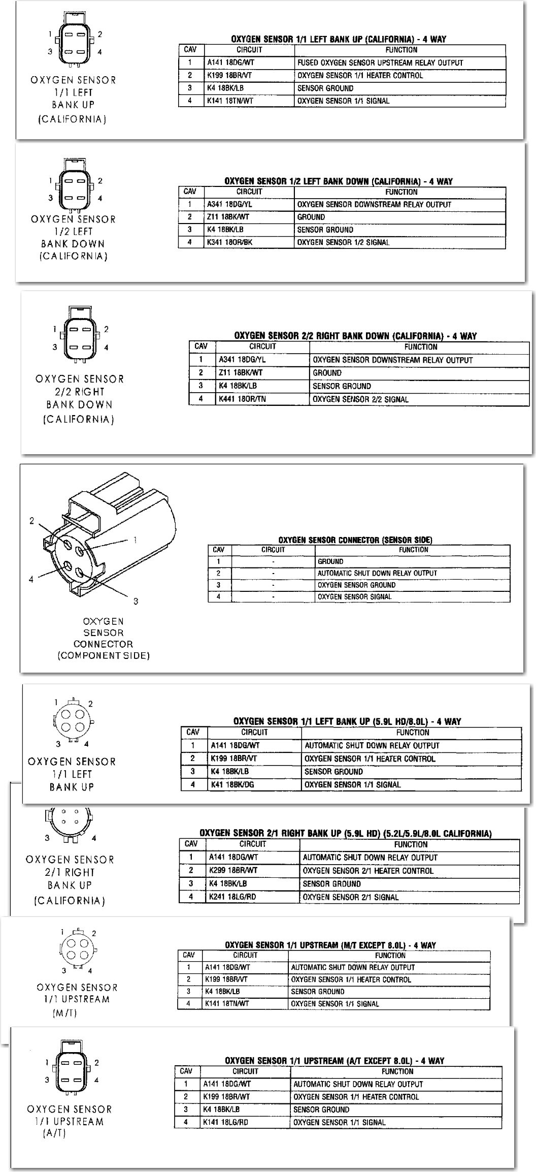
Dodge Ram 1500 O2 Sensor Wiring Q A On 4 Wire Diagrams
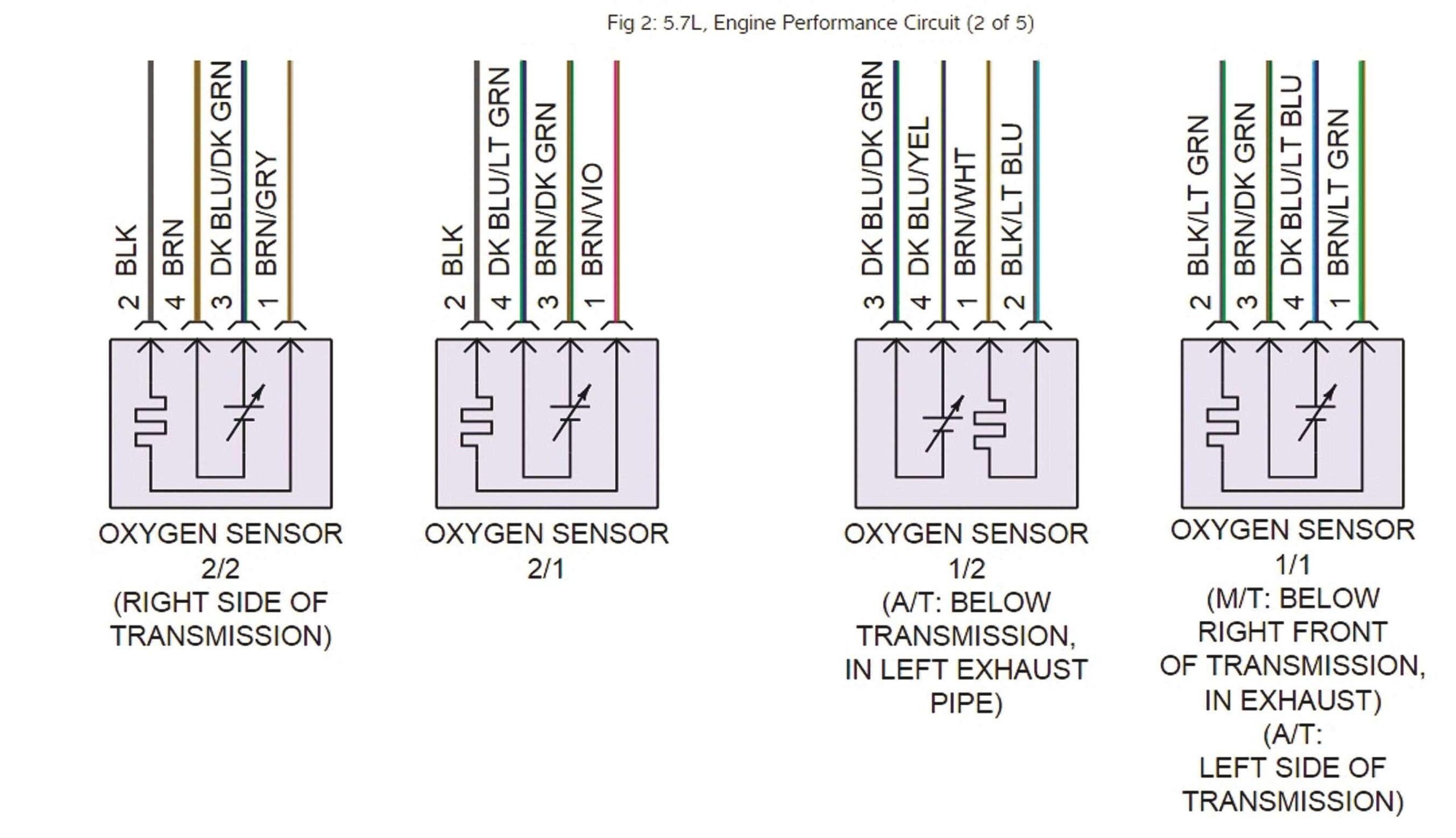
The image title is Dodge Ram 1500 O2 Sensor Wiring Q A On 4 Wire Diagrams, features dimensions of width 1056 px and height 2307 px, with a file size of 1056 x 2307. This image image/jpeg type visual are source from www.justanswer.com.
Tracing Sensor Wiring And Checking For Lazy Sensors Issuu
The image title is Tracing Sensor Wiring And Checking For Lazy Sensors Issuu, features dimensions of width 2560 px and height 1475 px, with a file size of 2702 x 1557. This image image/jpeg type visual are source from issuu.com
Sensor Schematics At DuckDuckGo Electronic Schematics Sensor Diagram
The image title is Sensor Schematics At DuckDuckGo Electronic Schematics Sensor Diagram, features dimensions of width 574 px and height 534 px, with a file size of 574 x 534. This image image/jpeg type visual are source from www.pinterest.com.
Toyota Oxygen Sensor Pinout 4 Sensor Toyota Oxygen
The image title is Toyota Oxygen Sensor Pinout 4 Sensor Toyota Oxygen, features dimensions of width 560 px and height 585 px, with a file size of 560 x 585. This image image/jpeg type visual are source from www.pinterest.com.
UNIVERSAL LAMBDA SENSOR OXYGEN SENSOR 4 WIRE HIGH QUALITY Automotive Repair Map Sensor Engine Control Unit
The image title is UNIVERSAL LAMBDA SENSOR OXYGEN SENSOR 4 WIRE HIGH QUALITY Automotive Repair Map Sensor Engine Control Unit, features dimensions of width 460 px and height 421 px, with a file size of 460 x 421.
The images on this page, sourced from Google for educational purposes, may be copyrighted. If you own an image and wish its removal or have copyright concerns, please contact us. We aim to promptly address these issues in compliance with our copyright policy and DMCA standards. Your cooperation is appreciated.
Related Keywords to 4 Wire O2 Sensor Wiring Diagram:
4 wire o2 sensor wiring diagram,4 wire o2 sensor wiring diagram dodge,4 wire o2 sensor wiring diagram honda,4 wire o2 sensor wiring diagram nissan,4 wire o2 sensor wiring diagram toyota
