Table of Contents
The Value of 4 Pin Alternator Wiring Diagram
When it comes to understanding the intricate workings of vehicle electrical systems, having a clear and comprehensive wiring diagram is essential. In the realm of alternator wiring, the 4 pin alternator wiring diagram stands out as a valuable resource for mechanics, DIY enthusiasts, and anyone looking to delve into the world of automotive electrics. This diagram serves as a roadmap, guiding individuals through the process of connecting and configuring the various components of a 4 pin alternator system.
The Basics of 4 Pin Alternator Wiring
Before diving into the specifics of the wiring diagram, it’s important to grasp the fundamental aspects of a 4 pin alternator setup. This type of alternator typically features four terminals: B+ (battery positive), B- (battery negative), S (sense), and L (lamp). Each terminal plays a crucial role in the overall functionality of the alternator, ensuring that the system operates efficiently and effectively.
Understanding the Wiring Diagram
The 4 pin alternator wiring diagram serves as a visual representation of how each terminal connects to the corresponding components within the system. By following the diagram, individuals can identify the proper placement of wires, determine the correct voltage and current flow, and troubleshoot any issues that may arise during installation or operation.
Benefits of Using a Wiring Diagram
One of the key advantages of utilizing a 4 pin alternator wiring diagram is the clarity it provides in terms of connectivity and configuration. Whether you’re replacing an old alternator or upgrading to a higher capacity model, having a detailed diagram at your disposal can streamline the process and minimize the risk of errors.
- Ensures correct wiring connections
- Facilitates troubleshooting and diagnostics
- Improves overall efficiency and performance
Step-by-Step Guide to Wiring a 4 Pin Alternator
- Identify the terminals on the alternator (B+, B-, S, L)
- Refer to the wiring diagram for proper wire placement
- Connect the B+ terminal to the positive battery terminal
- Attach the B- terminal to the negative battery terminal
- Connect the S and L terminals as indicated in the diagram
- Double-check all connections and secure them properly
Conclusion
In conclusion, the 4 pin alternator wiring diagram serves as a valuable tool for anyone seeking to navigate the complexities of automotive electrical systems. By understanding the basics of alternator wiring, utilizing a detailed diagram, and following a systematic approach to installation, individuals can ensure the proper functioning of their vehicle’s electrical system. With the right knowledge and resources at their disposal, tackling alternator wiring becomes a manageable task that yields rewarding results.
Related to 4 Pin Alternator Wiring Diagram
- 4 Ohm To 2 Ohm Wiring Diagram
- 4 Ohm Wiring Diagram
- 4 Pin 4 Wire Trailer Wiring Diagram
- 4 Pin 4 Wire Trailer Wiring Diagram Troubleshooting
- 4 Pin 5 Wire Trailer Wiring Diagram
4 Pin To 4 Pin Alternator Generator Adapter
The image title is 4 Pin To 4 Pin Alternator Generator Adapter, features dimensions of width 2000 px and height 1280 px, with a file size of 2000 x 1280 px. This image image/jpeg type visual are source from bp-automotive.com.
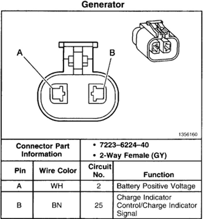
Dirty Dingo Motorsports
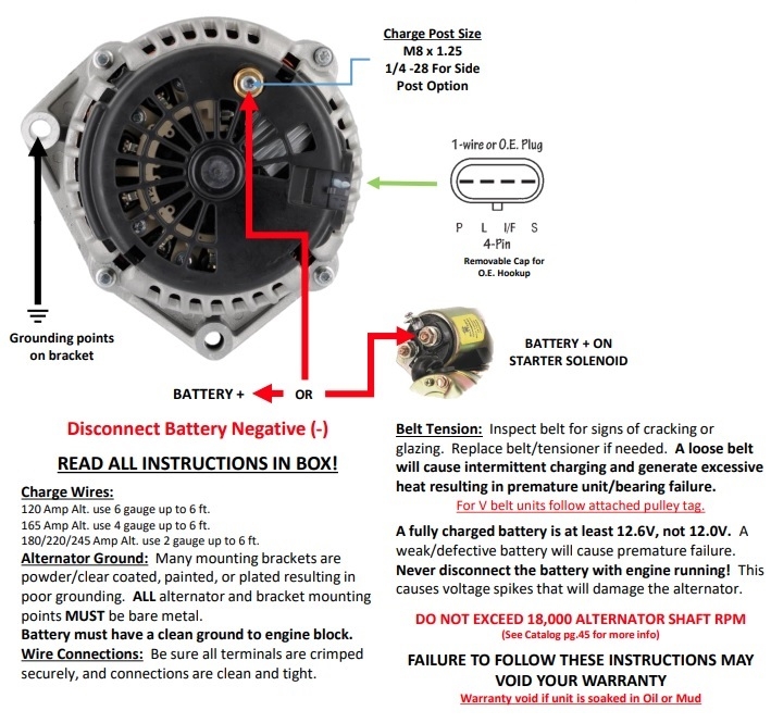
The image title is Dirty Dingo Motorsports, features dimensions of width 703 px and height 755 px, with a file size of 703 x 755 px. This image image/jpeg type visual are source from www.dirtydingo.com.
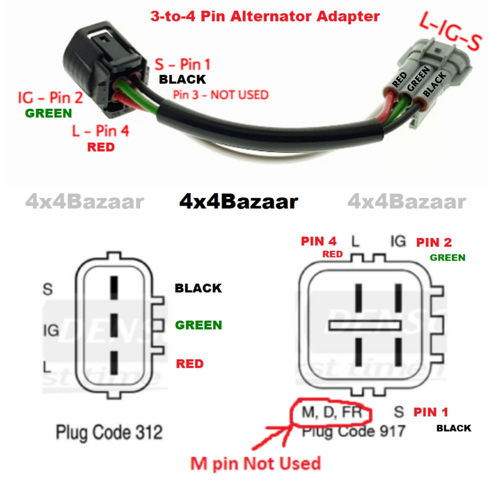
3 To 4 Pin Toyota Lexus Denso Alternator Adapter For Alternator Upgrade Swap EBay
The image title is 3 To 4 Pin Toyota Lexus Denso Alternator Adapter For Alternator Upgrade Swap EBay, features dimensions of width 1600 px and height 1575 px, with a file size of 1600 x 1575. This image image/jpeg type visual are source from www.ebay.com.
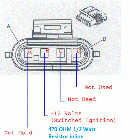
Dirty Dingo Motorsports
The image title is Dirty Dingo Motorsports, features dimensions of width 475 px and height 475 px, with a file size of 475 x 475. This image image/gif type visual are source from www.dirtydingo.com.
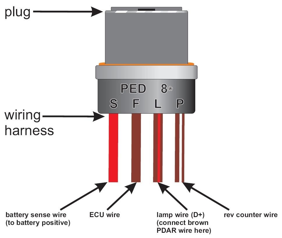
Alternator Lamp Wire Wire
The image title is Alternator Lamp Wire Wire, features dimensions of width 969 px and height 819 px, with a file size of 969 x 819. This image image/jpeg type visual are source from www.pinterest.com
4 Wire Alternator Wiring Diagram EdrawMax EdrawMax Templates
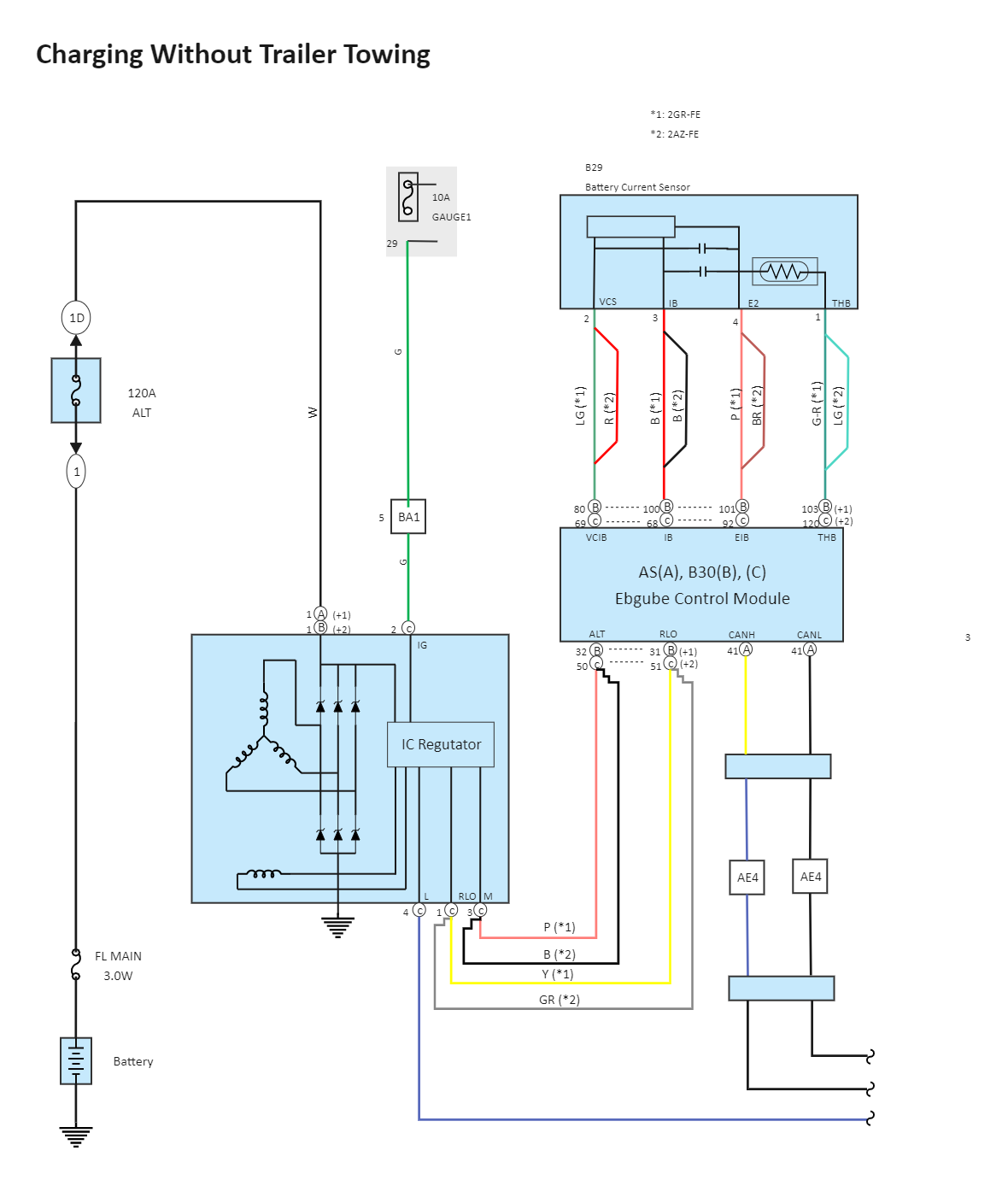
The image title is 4 Wire Alternator Wiring Diagram EdrawMax EdrawMax Templates, features dimensions of width 1180 px and height 1381 px, with a file size of 1180 x 1381. This image image/png type visual are source from www.edrawmax.com.
Testing Toyota Car Alternator S 4 Pin AVR Step By Step Guide YouTube
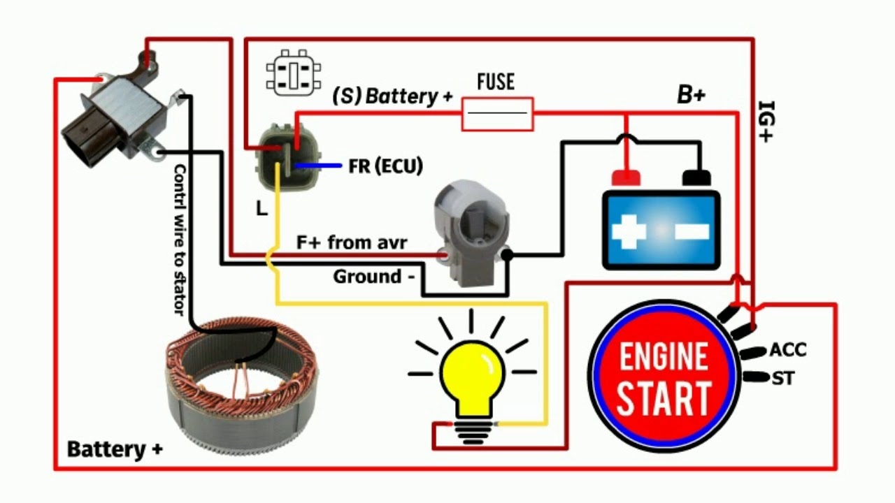
The image title is Testing Toyota Car Alternator S 4 Pin AVR Step By Step Guide YouTube, features dimensions of width 1280 px and height 720 px, with a file size of 1280 x 720. This image image/jpeg type visual are source from m.youtube.com.
Dirty Dingo Motorsports
The image title is Dirty Dingo Motorsports, features dimensions of width 709 px and height 665 px, with a file size of 709 x 665.
The images on this page, sourced from Google for educational purposes, may be copyrighted. If you own an image and wish its removal or have copyright concerns, please contact us. We aim to promptly address these issues in compliance with our copyright policy and DMCA standards. Your cooperation is appreciated.
Related Keywords to 4 Pin Alternator Wiring Diagram:
4 pin alternator wiring diagram,4 pin alternator wiring diagram pdf,4 prong alternator wiring diagram,gm 4 pin alternator wiring diagram,toyota 4 pin alternator wiring diagram

