Table of Contents
The Power of a 3 Wire Throttle Position Sensor Wiring Diagram
If you’re looking to optimize the performance of your vehicle’s engine, understanding the intricacies of the throttle position sensor (TPS) wiring diagram is crucial. Among the various types of TPS configurations, the 3 wire setup stands out for its simplicity and effectiveness. By delving into the details of a 3 wire throttle position sensor wiring diagram, you can unlock the full potential of your engine and ensure smooth operation at all times.
Understanding the Basics
Before we dive into the specifics of the wiring diagram, let’s first establish a solid foundation by understanding the basic function of the throttle position sensor. Essentially, the TPS monitors the position of the throttle valve and sends this information to the engine control unit (ECU). This data is crucial for determining the appropriate air-fuel mixture and ignition timing, ultimately impacting the performance and efficiency of the engine.
Decoding the Wiring Diagram
Now, let’s dissect the components of a 3 wire throttle position sensor wiring diagram. This setup typically consists of three wires: signal, ground, and 5V reference. The signal wire carries the input from the sensor to the ECU, while the ground wire provides the necessary return path for the circuit. The 5V reference wire supplies a constant voltage to power the sensor.
- Signal Wire: Carries input from sensor to ECU
- Ground Wire: Provides return path for circuit
- 5V Reference Wire: Supplies constant voltage to power sensor
Benefits of a 3 Wire Configuration
The 3 wire TPS wiring diagram offers several advantages over other setups. Firstly, the simplicity of the design makes it easier to troubleshoot and diagnose any potential issues. Additionally, the separate ground wire ensures a clean and stable signal, minimizing the risk of interference or inaccuracies in sensor readings.
Installation and Calibration
When it comes to installing and calibrating a 3 wire throttle position sensor, precision is key. Proper alignment and secure connections are essential to ensure accurate readings and optimal performance. Calibration may be required to synchronize the sensor with the ECU and fine-tune the throttle response for optimal engine efficiency.
- Ensure secure connections for all wires
- Calibrate sensor to synchronize with ECU
- Fine-tune throttle response for optimal performance
Conclusion
In conclusion, a 3 wire throttle position sensor wiring diagram is a valuable tool for maximizing the performance and efficiency of your engine. By understanding the intricacies of this setup and following proper installation and calibration procedures, you can unleash the full potential of your vehicle’s powertrain. Whether you’re a seasoned mechanic or an enthusiast looking to enhance your ride, mastering the nuances of the TPS wiring diagram is a worthwhile endeavor.
Related to 3 Wire Throttle Position Sensor Wiring Diagram
- 3 Wire Stove Plug Wiring Diagram
- 3 Wire Switch Wiring Diagram
- 3 Wire Tail Light Wiring Diagram
- 3 Wire Thermostat Wiring Diagram
- 3 Wire Thermostat Wiring Diagram Heat Only
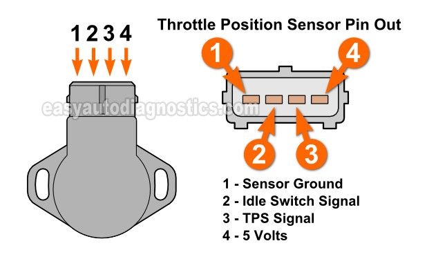
How To Test The Throttle Position Sensor 3 0L Mitsubishi Montero Automotive Repair Shop Mitsubishi Alternator Working
The image title is How To Test The Throttle Position Sensor 3 0L Mitsubishi Montero Automotive Repair Shop Mitsubishi Alternator Working, features dimensions of width 618 px and height 375 px, with a file size of 618 x 375 px. This image image/jpeg type visual are source from co.pinterest.com.
LS TPS 3 Wire Pigtail Throttle Position Sensor Connector LS1 LSX Plug WPTPS30 ICT Billet
The image title is LS TPS 3 Wire Pigtail Throttle Position Sensor Connector LS1 LSX Plug WPTPS30 ICT Billet, features dimensions of width 700 px and height 560 px, with a file size of 700 x 560 px. This image image/jpeg type visual are source from www.ictbillet.com.
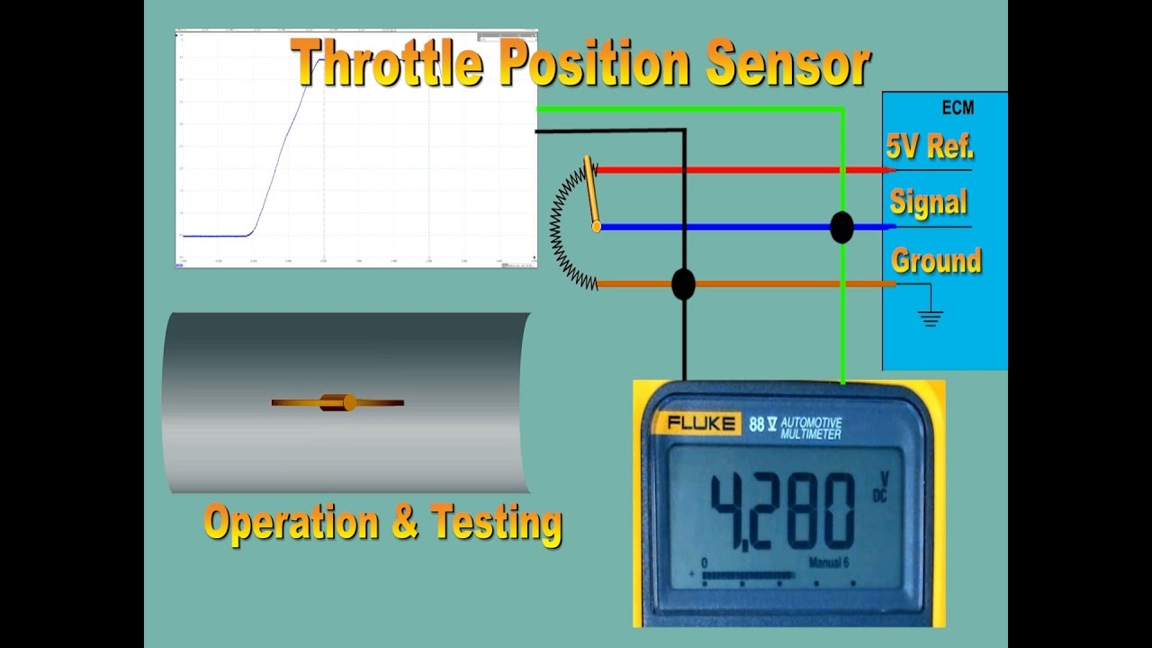
Throttle Position Sensor Testing And Explanation YouTube
The image title is Throttle Position Sensor Testing And Explanation YouTube, features dimensions of width 1280 px and height 720 px, with a file size of 1280 x 720. This image image/jpeg type visual are source from m.youtube.com.
GSIC Global Service Information Center
The image title is GSIC Global Service Information Center, features dimensions of width 333 px and height 445 px, with a file size of 333 x 445. This image image/png type visual are source from skcmspvtltd.org.
Chevrolet Blazer Questions Where S The Throttle Positioning Sensor CarGurus
The image title is Chevrolet Blazer Questions Where S The Throttle Positioning Sensor CarGurus, features dimensions of width 357 px and height 246 px, with a file size of 357 x 246. This image image/jpeg type visual are source from www.cargurus.com
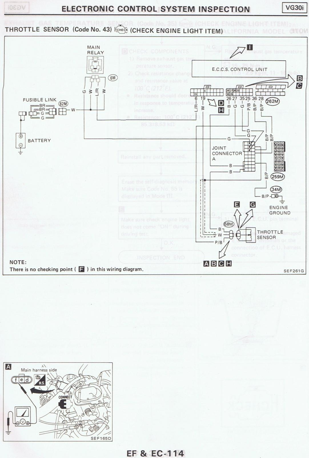
87 Pathfinder TPS Wiring Diagram 86 5 89 WD21 Pathfinders NPORA Forums
The image title is 87 Pathfinder TPS Wiring Diagram 86 5 89 WD21 Pathfinders NPORA Forums, features dimensions of width 1082 px and height 1600 px, with a file size of 1082 x 1600. This image image/jpeg type visual are source from www.nissanpathfinders.net.
Toyota TPS And APS Wiring Diagram G4x Forums Link Engine Management
The image title is Toyota TPS And APS Wiring Diagram G4x Forums Link Engine Management, features dimensions of width 1056 px and height 1472 px, with a file size of 1056 x 1472. This image image/png type visual are source from forums.linkecu.com.
Chevrolet Throttle Position Sensor Diagnosis And Repair Help Throttle Sensor Custom Chevy Trucks
The image title is Chevrolet Throttle Position Sensor Diagnosis And Repair Help Throttle Sensor Custom Chevy Trucks, features dimensions of width 650 px and height 300 px, with a file size of 650 x 300.
The images on this page, sourced from Google for educational purposes, may be copyrighted. If you own an image and wish its removal or have copyright concerns, please contact us. We aim to promptly address these issues in compliance with our copyright policy and DMCA standards. Your cooperation is appreciated.
Related Keywords to 3 Wire Throttle Position Sensor Wiring Diagram:
3 wire throttle position sensor wiring diagram,how does a 3 wire crank sensor work,how to test a 3 wire throttle position sensor,throttle position sensor wire colors,toyota 3 wire throttle position sensor wiring diagram


