Table of Contents
Exploring the 3 Wire Mass Air Flow Sensor Wiring Diagram
The Value of Understanding the 3 Wire Mass Air Flow Sensor Wiring Diagram
When it comes to the intricate workings of a vehicle’s engine, one crucial component that plays a significant role in ensuring optimal performance is the Mass Air Flow (MAF) sensor. More specifically, the 3 wire MAF sensor wiring diagram serves as a foundational blueprint for connecting this essential sensor to the vehicle’s electrical system. By delving into the intricacies of this diagram, automotive enthusiasts and technicians alike can unlock a deeper understanding of how the MAF sensor functions and how it contributes to overall engine efficiency. Let’s explore the nuances of the 3 wire MAF sensor wiring diagram and uncover the insights it holds for anyone seeking to enhance their knowledge of automotive electronics.
Understanding the Basics of a 3 Wire Mass Air Flow Sensor
Before diving into the wiring diagram itself, it’s essential to grasp the fundamental principles behind a 3 wire Mass Air Flow sensor. This sensor is designed to measure the amount of air entering the engine, playing a critical role in determining the air-fuel ratio for proper combustion. With three wires responsible for power, ground, and signal transmission, understanding how these connections interact is key to ensuring the sensor operates correctly. By comprehending the intricacies of each wire’s function, technicians can troubleshoot issues effectively and optimize the sensor’s performance.
Deciphering the Wiring Diagram
The 3 wire MAF sensor wiring diagram provides a detailed depiction of how each wire should be connected within the vehicle’s electrical system. From identifying the power source to understanding where the signal wire should be linked, this diagram acts as a roadmap for ensuring proper installation and functionality of the MAF sensor. By dissecting each component of the wiring diagram, technicians can troubleshoot connectivity issues, verify correct wiring configurations, and optimize the sensor’s performance for improved engine efficiency.
Tips for Proper Installation
Double-check wire color coding to ensure accurate connections.
Use a multimeter to test continuity and ensure proper voltage flow.
Secure all connections to prevent loose wiring and potential electrical issues.
Consult the vehicle’s service manual for specific wiring diagrams and instructions.
Enhancing Engine Performance Through Proper Wiring
By honing in on the intricacies of the 3 wire Mass Air Flow sensor wiring diagram, automotive enthusiasts and technicians can elevate their understanding of this critical component and its impact on engine performance. From troubleshooting connectivity issues to optimizing sensor functionality, a comprehensive grasp of the wiring diagram empowers individuals to fine-tune their vehicles for peak efficiency. Whether you’re a seasoned technician or an aspiring automotive enthusiast, exploring the nuances of the 3 wire MAF sensor wiring diagram opens up a world of possibilities for enhancing engine performance and delving deeper into the realm of automotive electronics.
Related to 3 Wire Mass Air Flow Sensor Wiring Diagram
- 3 Wire Headlight Wiring Diagram
- 3 Wire Led Light Bar Wiring Diagram
- 3 Wire Led Light Wiring Diagram
- 3 Wire Led Tail Light Wiring Diagram
- 3 Wire Maf Sensor Wiring Diagram
LS3 LS7 Mass Air Flow Connector Pigtail
The image title is LS3 LS7 Mass Air Flow Connector Pigtail, features dimensions of width 2000 px and height 1539 px, with a file size of 2000 x 1539 px. This image image/png type visual are source from bp-automotive.com.
Amazon Michigan Motorsports LS Gen 3 Mass Air Flow MAF Connector 3 Wire Sensor Pigtail Wiring LS1 5 7L Automotive
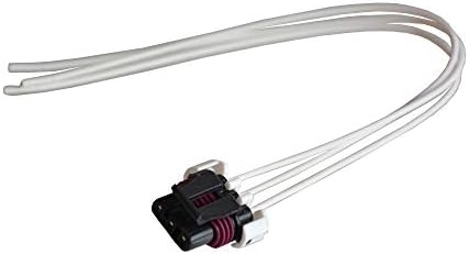
The image title is Amazon Michigan Motorsports LS Gen 3 Mass Air Flow MAF Connector 3 Wire Sensor Pigtail Wiring LS1 5 7L Automotive, features dimensions of width 427 px and height 231 px, with a file size of 427 x 231 px. This image image/jpeg type visual are source from www.amazon.com.
LS1 3 MAF Wire Harness To LS3 5 Wire MAF Sensor Adapter LS7 Mass Air Flow Meter EBay
The image title is LS1 3 MAF Wire Harness To LS3 5 Wire MAF Sensor Adapter LS7 Mass Air Flow Meter EBay, features dimensions of width 400 px and height 400 px, with a file size of 400 x 400. This image image/jpeg type visual are source from www.ebay.com.
GM 5 Wire MAF Sensor Wiring Diagram JustAnswer Q A
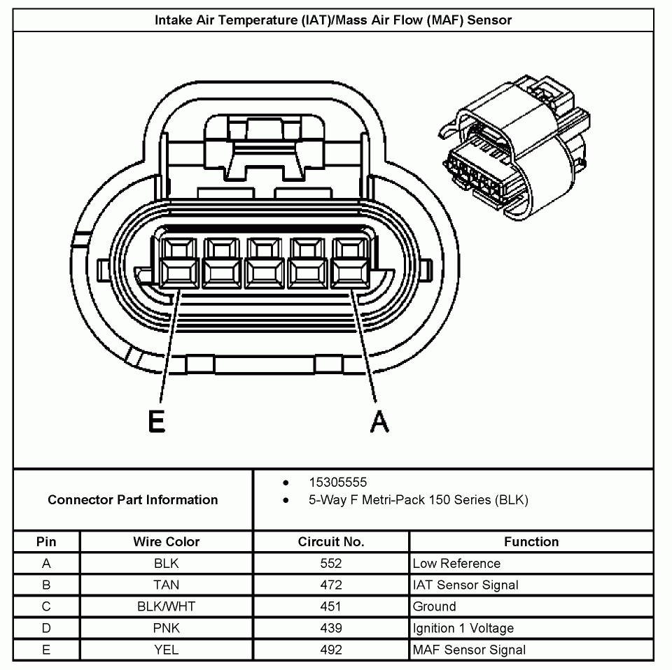
The image title is GM 5 Wire MAF Sensor Wiring Diagram JustAnswer Q A, features dimensions of width 960 px and height 958 px, with a file size of 960 x 958. This image image/gif type visual are source from www.justanswer.com.
Amazon ICT Billet LS Mass Air Flow Connector 5 Wire Pigtail Gen 3 WPMAF30 Automotive
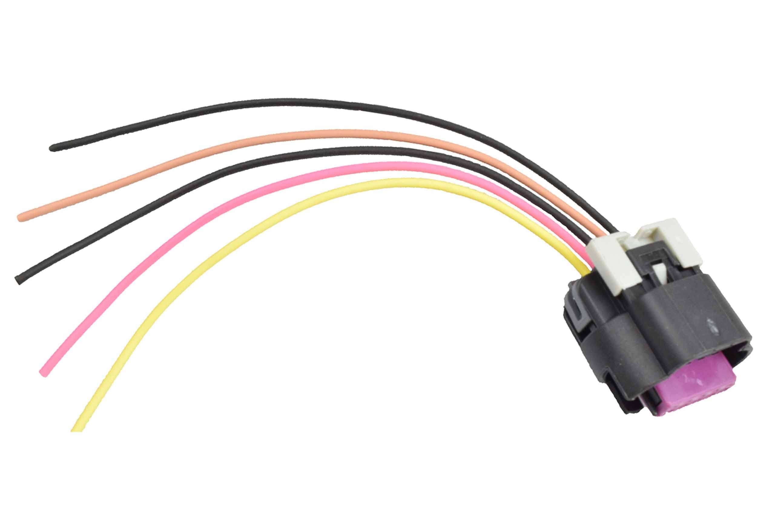
The image title is Amazon ICT Billet LS Mass Air Flow Connector 5 Wire Pigtail Gen 3 WPMAF30 Automotive, features dimensions of width 2560 px and height 1707 px, with a file size of 2560 x 1707. This image image/jpeg type visual are source from www.amazon.com
Amazon Michigan Motorsports LS Gen 3 Mass Air Flow MAF Connector 3 Wire Sensor Pigtail Wiring LS1 5 7L Automotive
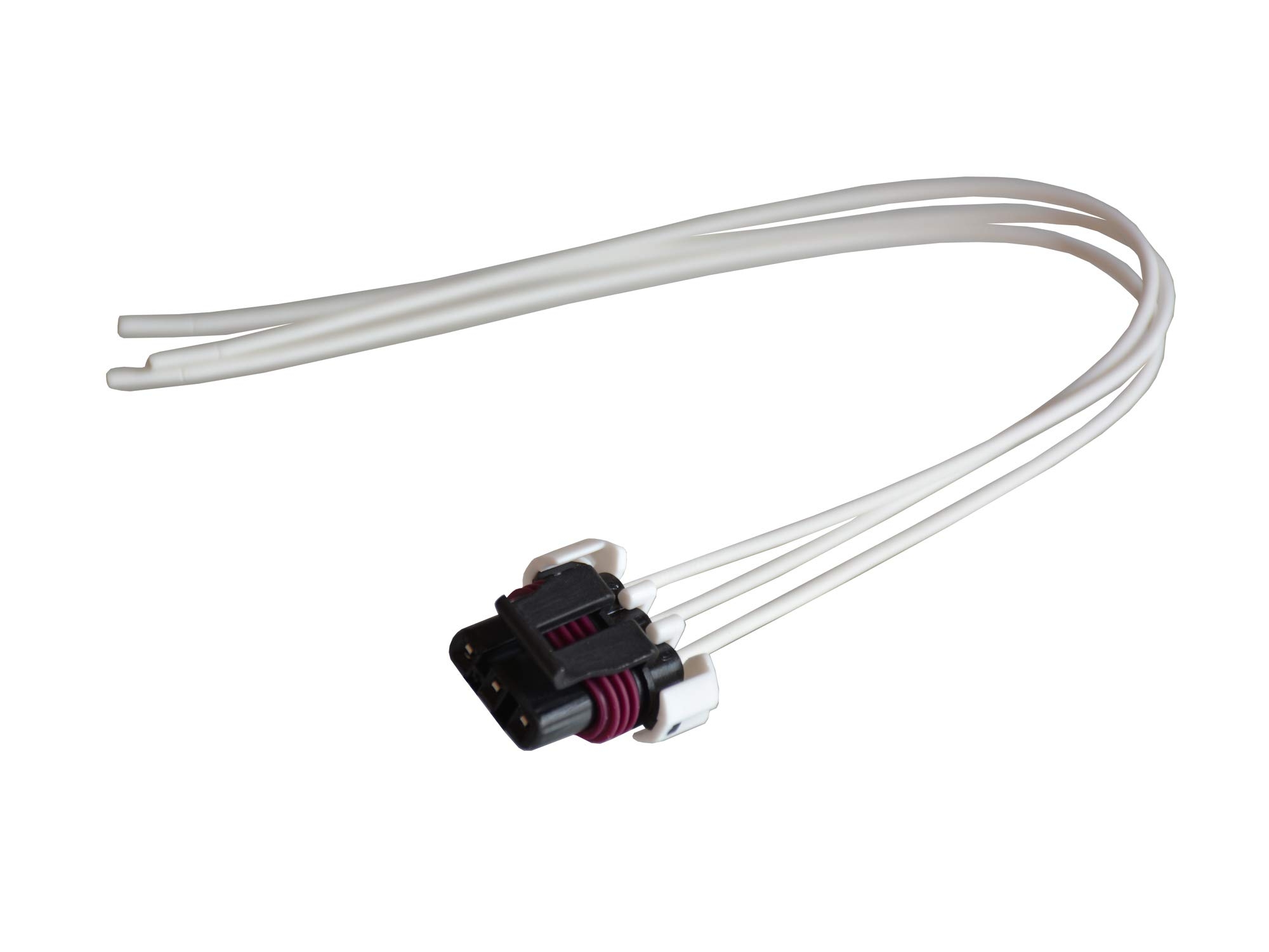
The image title is Amazon Michigan Motorsports LS Gen 3 Mass Air Flow MAF Connector 3 Wire Sensor Pigtail Wiring LS1 5 7L Automotive, features dimensions of width 2000 px and height 1500 px, with a file size of 2000 x 1500. This image image/jpeg type visual are source from www.amazon.com.
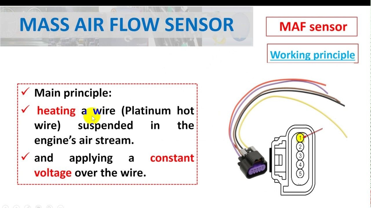
Mass Air Flow Sensor Hot Wire Symptoms Of A Bad MAF Sensor YouTube Sensor Flow Mass
The image title is Mass Air Flow Sensor Hot Wire Symptoms Of A Bad MAF Sensor YouTube Sensor Flow Mass, features dimensions of width 1280 px and height 720 px, with a file size of 1280 x 720. This image image/jpeg type visual are source from www.pinterest.com.
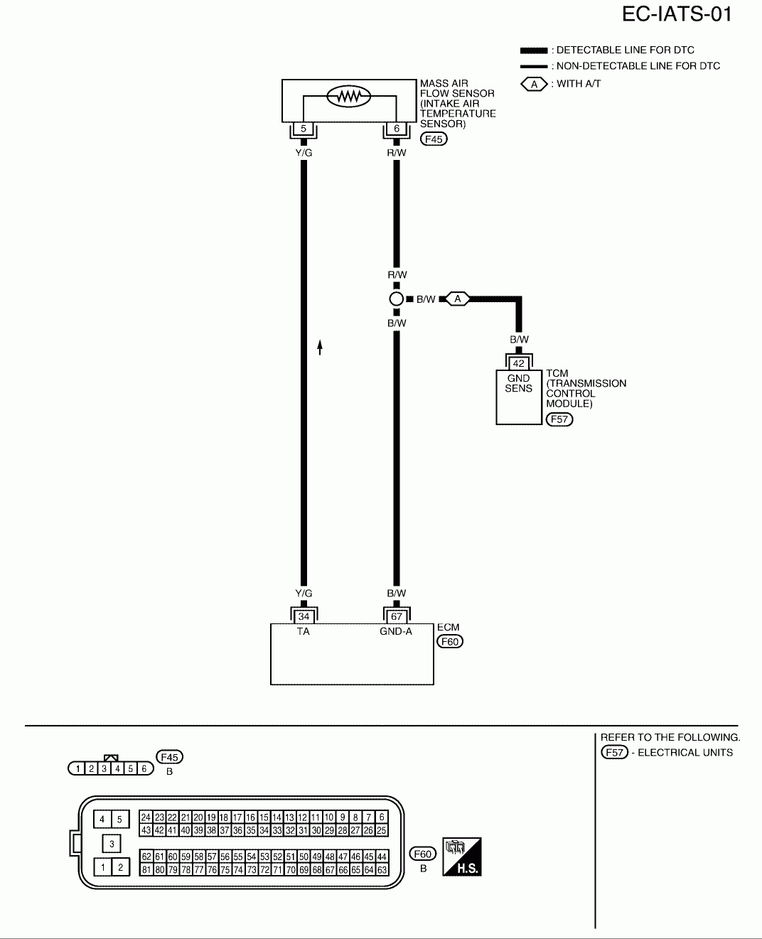
Nissan MAF Sensor Wiring Diagram Q A For 3 4 And 5 Wire Mass Air Flow
The image title is Nissan MAF Sensor Wiring Diagram Q A For 3 4 And 5 Wire Mass Air Flow, features dimensions of width 1072 px and height 1321 px, with a file size of 1072 x 1321.
The images on this page, sourced from Google for educational purposes, may be copyrighted. If you own an image and wish its removal or have copyright concerns, please contact us. We aim to promptly address these issues in compliance with our copyright policy and DMCA standards. Your cooperation is appreciated.
Related Keywords to 3 Wire Mass Air Flow Sensor Wiring Diagram:
3 wire mass air flow sensor wiring diagram,how does a hot wire maf sensor work,how to replace mass air flow sensor wiring,how to test 3 wire maf sensor,how to test maf sensor wiring
