Table of Contents
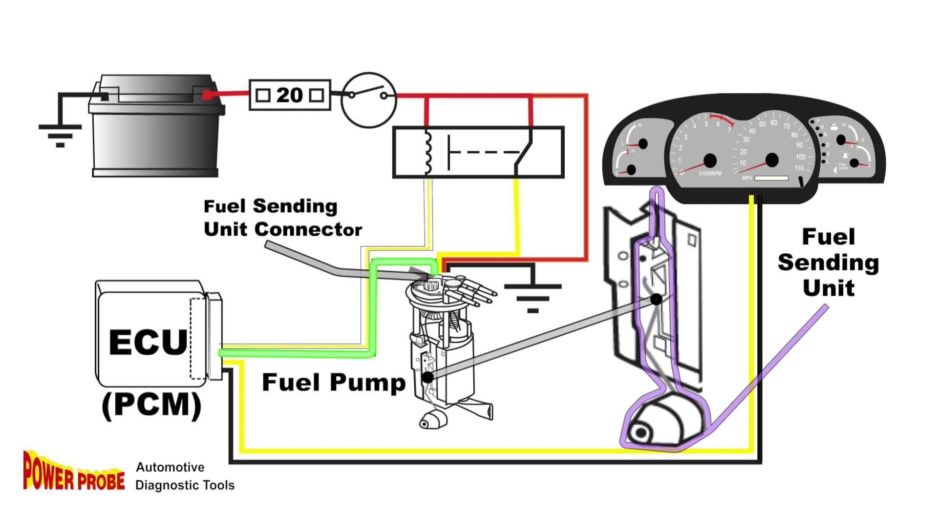
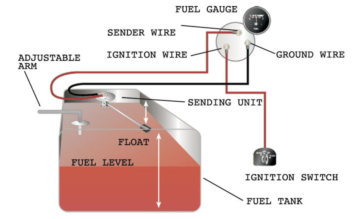
3 Wire Fuel Sending Unit Wiring Diagram
Unlocking the Mystery of 3 Wire Fuel Sending Unit Wiring Diagram
When it comes to understanding the intricate workings of your vehicle’s fuel system, having a reliable wiring diagram can make all the difference. The 3 wire fuel sending unit wiring diagram is a crucial piece of the puzzle that allows you to navigate the complexities of your fuel sending unit with ease. By unraveling the mysteries hidden within this diagram, you can gain valuable insights into how your fuel system operates, troubleshoot issues, and ensure optimal performance. Let’s delve into the world of 3 wire fuel sending unit wiring diagrams and uncover the secrets that lie beneath.
The Basics of a 3 Wire Fuel Sending Unit Wiring Diagram
At the core of every 3 wire fuel sending unit wiring diagram lies a detailed schematic that maps out the connections between the fuel sending unit and the vehicle’s electrical system. This diagram typically consists of three wires that control various functions of the fuel sending unit, such as measuring fuel levels, sending signals to the fuel gauge, and grounding the unit for accurate readings. Understanding the role of each wire and how they interact is essential for maintaining a properly functioning fuel system.
Wire Color Coding
One of the key elements of a 3 wire fuel sending unit wiring diagram is the color coding of the wires. Each wire is assigned a specific color to denote its purpose and function within the system. Common wire colors include black for ground, white for the sending unit signal, and red for power. By familiarizing yourself with these color codes, you can easily identify and troubleshoot any issues that may arise with your fuel sending unit.
Interpreting the Diagram
To make the most of a 3 wire fuel sending unit wiring diagram, it’s essential to understand how to interpret the information presented. This diagram will outline the connections between the fuel sending unit, fuel gauge, and the vehicle’s electrical system in a clear and concise manner. By following the pathways mapped out in the diagram, you can ensure that all components are properly connected and functioning as intended.
Benefits of Using a 3 Wire Fuel Sending Unit Wiring Diagram
Having a comprehensive wiring diagram for your 3 wire fuel sending unit offers numerous benefits for vehicle owners. By referring to this diagram, you can easily diagnose issues with your fuel system, identify faulty connections, and troubleshoot problems that may arise. Additionally, understanding the wiring configuration of your fuel sending unit can help you make informed decisions when performing maintenance or upgrades to your vehicle’s fuel system.
Troubleshooting Tips
Check for loose or corroded connections
Test the continuity of each wire using a multimeter
Inspect the fuel sending unit for any signs of damage
Upgrading Your Fuel System
Consider upgrading to a digital fuel gauge for improved accuracy
Install a high-quality fuel sending unit for reliable performance
Consult the wiring diagram when making any modifications to the fuel system
In conclusion, the 3 wire fuel sending unit wiring diagram serves as a valuable tool for understanding and maintaining your vehicle’s fuel system. By delving into the intricacies of this diagram, you can unlock a world of possibilities for optimizing your fuel system’s performance and ensuring smooth operation on the road. Whether you’re troubleshooting issues or planning upgrades, having a solid grasp of your fuel sending unit wiring diagram is essential for any vehicle owner. Embrace the power of knowledge and harness the potential of your fuel system with the insights provided by this invaluable resource.
Related to 3 Wire Fuel Sending Unit Wiring Diagram
- 3 Wire Exhaust Fan Wiring Diagram
- 3 Wire Exhaust Fan Wiring Diagram With Capacitor
- 3 Wire Fire Alarm Smoke Detector Wiring Diagram
- 3 Wire Ford Alternator Regulator Wiring Diagram
- 3 Wire Ford Alternator Wiring Diagram
Gauge Sending Unit Frequently Asked Questions KUS Americas Inc
The image title is Gauge Sending Unit Frequently Asked Questions KUS Americas Inc, features dimensions of width 874 px and height 559 px, with a file size of 874 x 559 px. This image image/jpeg type visual are source from kus-usa.com.
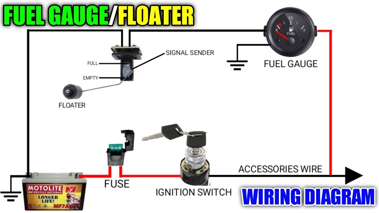
FUEL GAUGE FLOATER WIRING DIAGRAM FUNCTIONS AND CONNECTIONS YouTube
The image title is FUEL GAUGE FLOATER WIRING DIAGRAM FUNCTIONS AND CONNECTIONS YouTube, features dimensions of width 1280 px and height 720 px, with a file size of 1280 x 720 px. This image image/jpeg type visual are source from www.youtube.com.
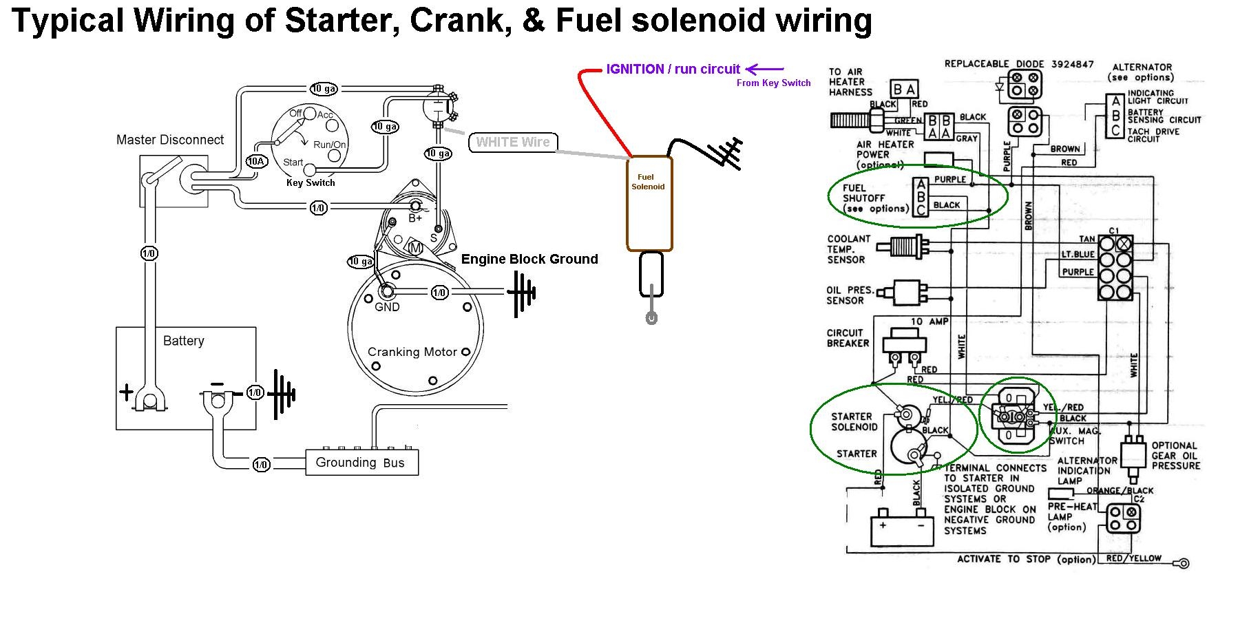
Fuel Shutoff Solenoid Wiring 101 Seaboard Marine
The image title is Fuel Shutoff Solenoid Wiring 101 Seaboard Marine, features dimensions of width 1830 px and height 902 px, with a file size of 1830 x 902. This image image/jpeg type visual are source from www.sbmar.com.
Push N Fuel System ATTA Tank
The image title is Push N Fuel System ATTA Tank, features dimensions of width 1738 px and height 1343 px, with a file size of 1738 x 1343. This image image/jpeg type visual are source from www.attatank.com.
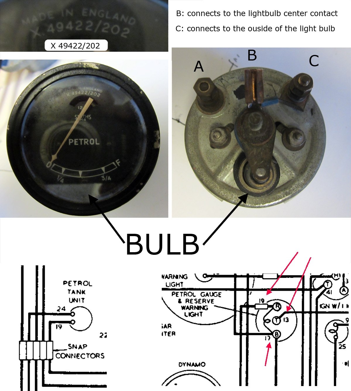
Fuel Gauge Wiring Problem XK Jag Lovers Forums
The image title is Fuel Gauge Wiring Problem XK Jag Lovers Forums, features dimensions of width 1200 px and height 1338 px, with a file size of 1200 x 1338. This image image/jpeg type visual are source from forums.jag-lovers.com
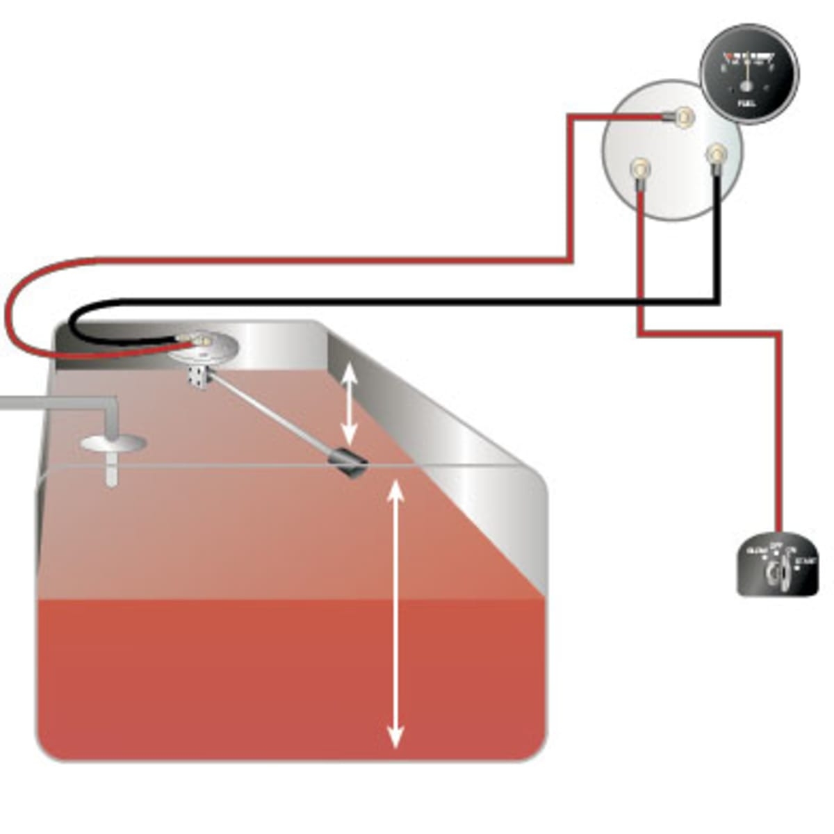
How To Test And Replace Your Fuel Gauge And Sending Unit Sail Magazine
The image title is How To Test And Replace Your Fuel Gauge And Sending Unit Sail Magazine, features dimensions of width 1200 px and height 1200 px, with a file size of 1200 x 1200. This image image/jpeg type visual are source from www.sailmagazine.com.
Fuel Gauge Sending Unit Wiring Diagram Diagram Light Switch Wiring The Unit
The image title is Fuel Gauge Sending Unit Wiring Diagram Diagram Light Switch Wiring The Unit, features dimensions of width 1920 px and height 1080 px, with a file size of 1920 x 1080. This image image/jpeg type visual are source from www.pinterest.com.
How To Test And Replace Your Fuel Gauge And Sending Unit Sail Magazine
The image title is How To Test And Replace Your Fuel Gauge And Sending Unit Sail Magazine, features dimensions of width 1200 px and height 737 px, with a file size of 1200 x 737.
The images on this page, sourced from Google for educational purposes, may be copyrighted. If you own an image and wish its removal or have copyright concerns, please contact us. We aim to promptly address these issues in compliance with our copyright policy and DMCA standards. Your cooperation is appreciated.
Related Keywords to 3 Wire Fuel Sending Unit Wiring Diagram:
3 wire fuel pressure sensor wiring diagram,3 wire fuel pump wiring diagram,3 wire fuel sender wiring diagram,3 wire fuel sending unit wiring diagram,what gauge wire for fuel sending unit

