Table of Contents
Exploring the Value of 3 Phase Contactor Wiring Diagram
The Value of 3 Phase Contactor Wiring Diagram
When it comes to electrical systems, understanding the intricacies of wiring diagrams is crucial for smooth operations and safety. One essential component in many industrial and commercial setups is the 3 phase contactor, which plays a vital role in controlling electrical circuits. A 3 phase contactor wiring diagram is not just a mere technical drawing; it is a roadmap that guides electricians and engineers in connecting the right wires to ensure proper functioning of equipment and machinery. Let’s delve into the importance and nuances of a 3 phase contactor wiring diagram to unravel its value in electrical systems.
The Basics of a 3 Phase Contactor Wiring Diagram
A 3 phase contactor wiring diagram typically depicts the connections between the contactor, the power source, and the load. It outlines the arrangement of the three phases (A, B, and C) along with the control circuitry, indicating how power flows through the system. By following the diagram meticulously, electricians can ensure that the right wires are connected to the appropriate terminals, preventing malfunctions and hazards.
Benefits of Using a 3 Phase Contactor Wiring Diagram
1. Prevents Errors: One of the primary advantages of a wiring diagram is that it minimizes the risk of wiring errors. By providing a clear visual representation of the connections, electricians can accurately wire the contactor, reducing the chances of faults or short circuits.
2. Troubleshooting Aid: In case of malfunctions or breakdowns, a well-documented wiring diagram serves as a valuable troubleshooting aid. Electricians can refer to the diagram to identify and rectify issues swiftly, saving time and effort in diagnosing electrical problems.
3. Standardization: Using a standardized wiring diagram ensures consistency in wiring practices across different installations. It promotes uniformity in electrical systems, making it easier for technicians to understand and work on various setups without confusion.
Steps to Interpret a 3 Phase Contactor Wiring Diagram
Conclusion
In conclusion, a 3 phase contactor wiring diagram is a valuable tool that enhances the efficiency and safety of electrical installations. By providing a detailed layout of connections and circuits, it empowers electricians to wire contactors correctly, troubleshoot issues effectively, and maintain consistency in wiring practices. Understanding and utilizing a wiring diagram not only streamlines the installation process but also contributes to the longevity and reliability of electrical systems. So, the next time you encounter a 3 phase contactor, remember the significance of referring to a well-crafted wiring diagram for a seamless electrical setup.
Related to 3 Phase Contactor Wiring Diagram
- 3 In 1 Bathroom Heater Wiring Diagram
- 3 Ph Motor Wiring Diagram
- 3 Phase 240v Wiring Diagram
- 3 Phase 480 To 240 Transformer Wiring Diagram
- 3 Phase Air Compressor Wiring Diagram
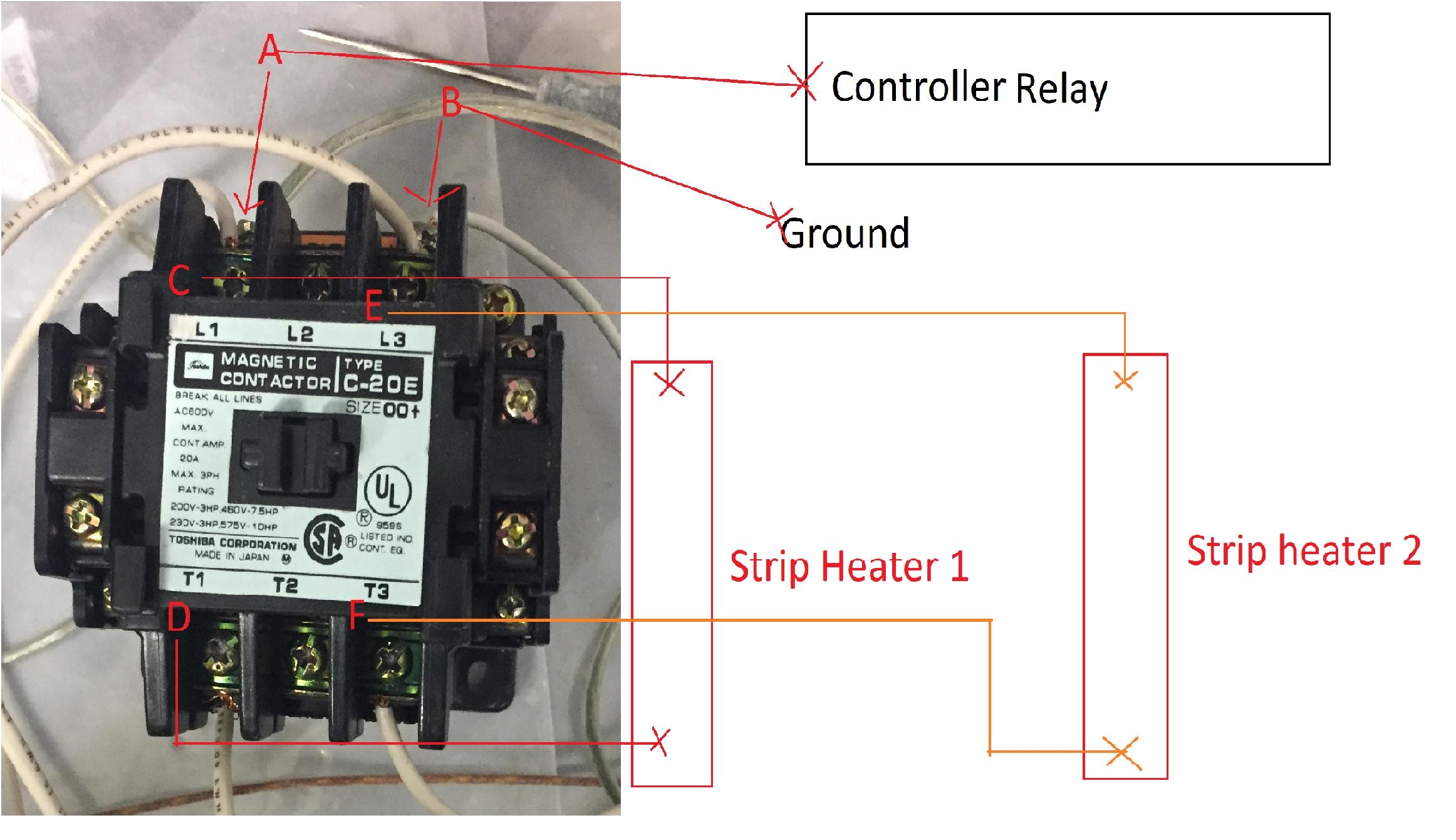
Power Supply Splitting A Three Phase Contactor Electrical Engineering Stack Exchange
The image title is Power Supply Splitting A Three Phase Contactor Electrical Engineering Stack Exchange, features dimensions of width 2324 px and height 1340 px, with a file size of 2324 x 1340 px. This image image/jpeg type visual are source from electronics.stackexchange.com.
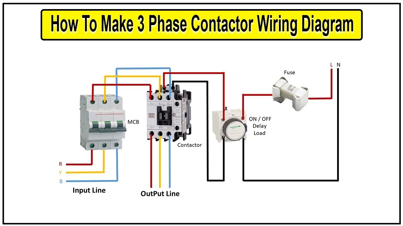
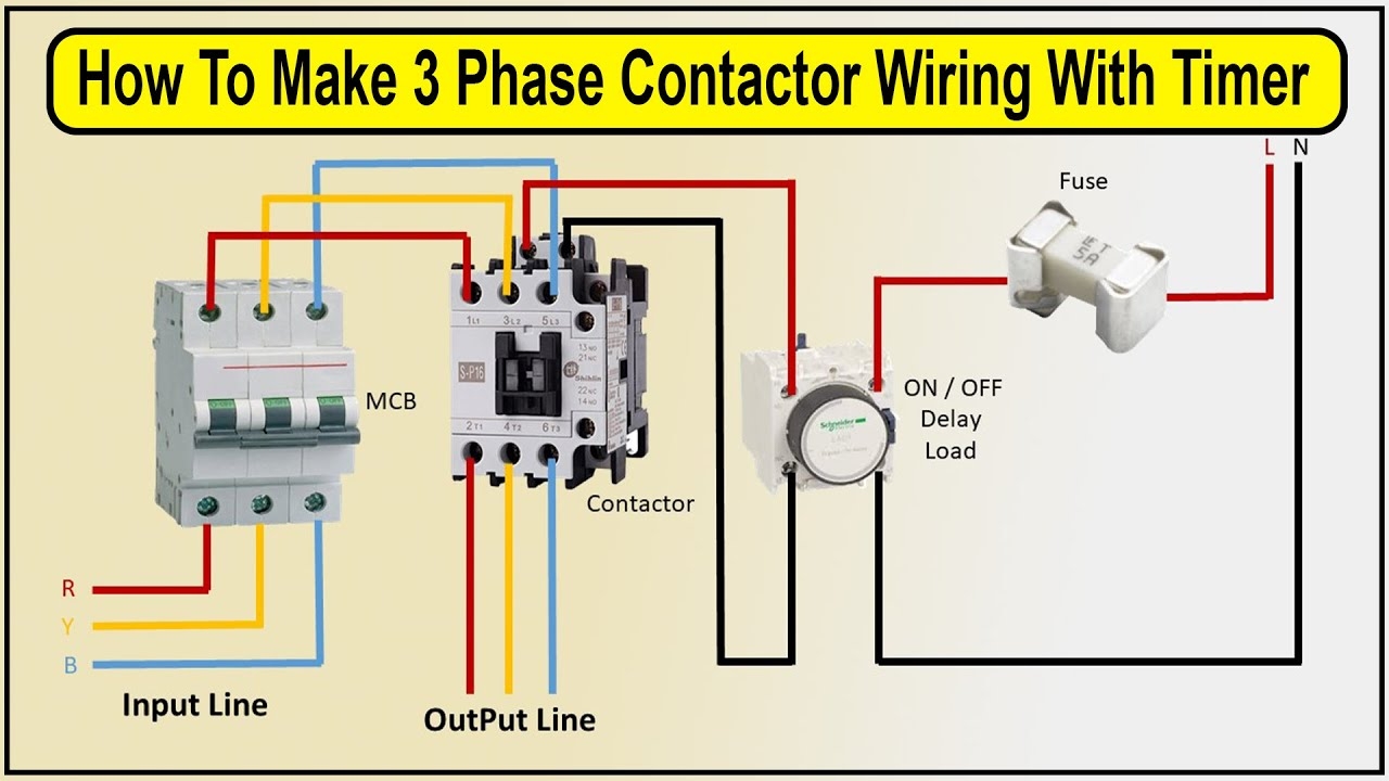
How To Make 3 Phase Contactor Wiring Diagram With Timer Connection Timer YouTube
The image title is How To Make 3 Phase Contactor Wiring Diagram With Timer Connection Timer YouTube, features dimensions of width 1280 px and height 720 px, with a file size of 1280 x 720 px. This image image/jpeg type visual are source from www.youtube.com.
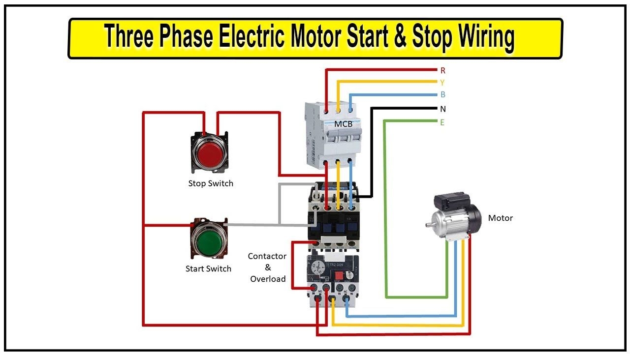
How To Wire A 3 Phase Electric Motor For Start And Stop
The image title is How To Wire A 3 Phase Electric Motor For Start And Stop, features dimensions of width 1280 px and height 720 px, with a file size of 1280 x 720. This image image/jpeg type visual are source from www.pinterest.com.
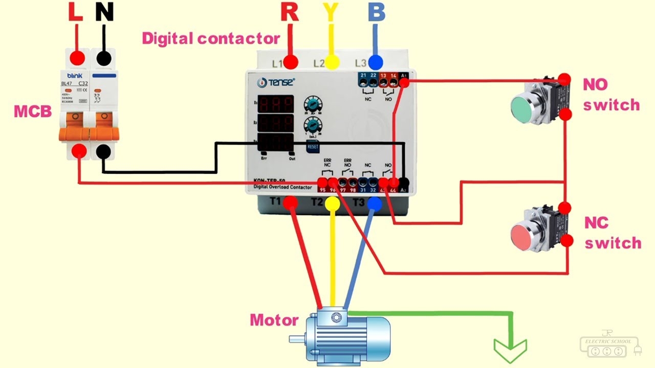
Digital Contactor 3 Phase Dol Starter Connection YouTube
The image title is Digital Contactor 3 Phase Dol Starter Connection YouTube, features dimensions of width 1280 px and height 720 px, with a file size of 1280 x 720. This image image/jpeg type visual are source from www.youtube.com.
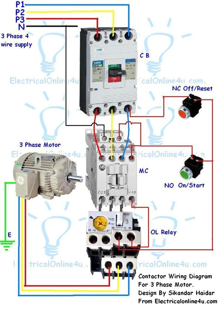
6372A1A Contactor Wiring Diagram Single Phase Circuit Diagram Electrical Circuit Diagram Electrical Wiring Diagram
The image title is 6372A1A Contactor Wiring Diagram Single Phase Circuit Diagram Electrical Circuit Diagram Electrical Wiring Diagram, features dimensions of width 736 px and height 1026 px, with a file size of 736 x 1026. This image image/jpeg type visual are source from www.pinterest.com
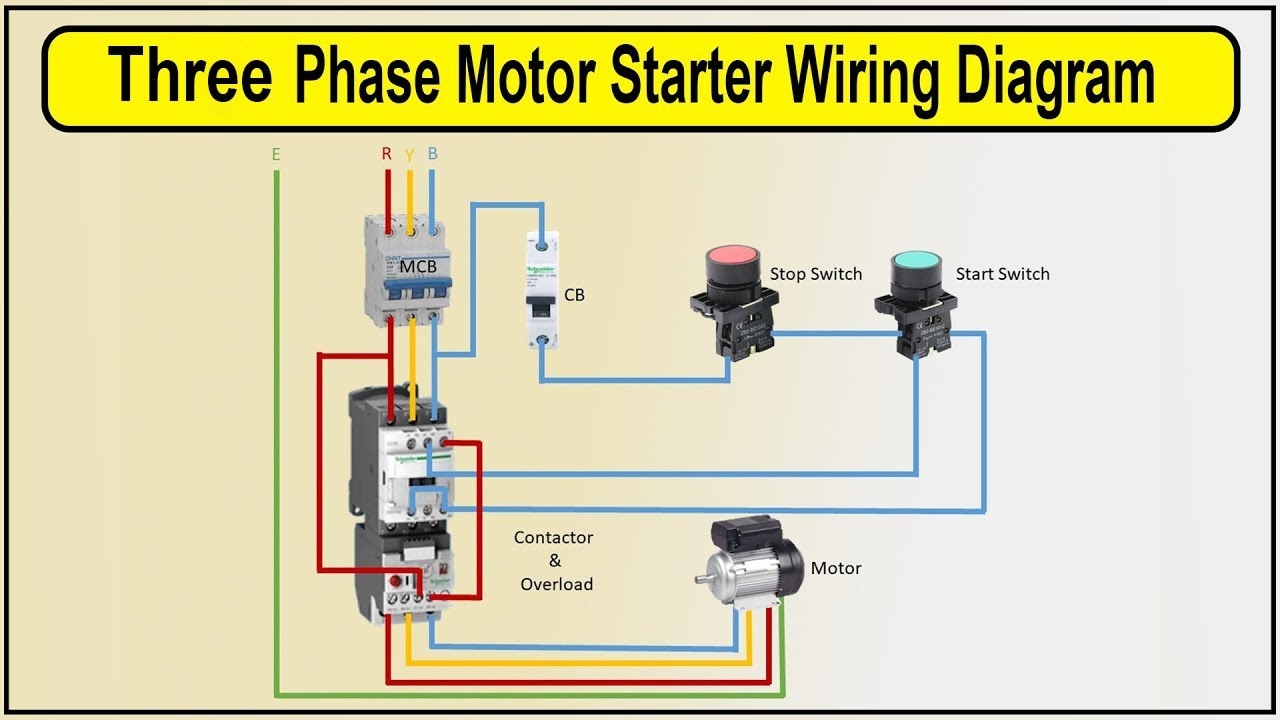
How To Make 3 Phase Motor Starter Wiring Diagram 3 Phase Motor Contactor Wiring Diagram YouTube
The image title is How To Make 3 Phase Motor Starter Wiring Diagram 3 Phase Motor Contactor Wiring Diagram YouTube, features dimensions of width 1280 px and height 720 px, with a file size of 1280 x 720. This image image/jpeg type visual are source from www.youtube.com.
How To Make 3 Phase Contactor Wiring Diagram With Timer Connection 3 Phase Timer Connection YouTube
The image title is How To Make 3 Phase Contactor Wiring Diagram With Timer Connection 3 Phase Timer Connection YouTube, features dimensions of width 1280 px and height 720 px, with a file size of 1280 x 720. This image image/jpeg type visual are source from m.youtube.com.
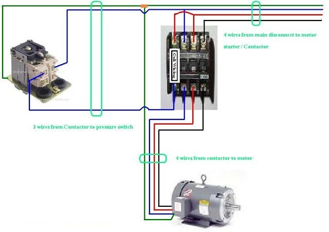
Three Phase Contactor Wiring Diagram Electrical Diagram Electrical Circuit Diagram Electrical Wiring Diagram
The image title is Three Phase Contactor Wiring Diagram Electrical Diagram Electrical Circuit Diagram Electrical Wiring Diagram, features dimensions of width 640 px and height 451 px, with a file size of 640 x 451.
The images on this page, sourced from Google for educational purposes, may be copyrighted. If you own an image and wish its removal or have copyright concerns, please contact us. We aim to promptly address these issues in compliance with our copyright policy and DMCA standards. Your cooperation is appreciated.
Related Keywords to 3 Phase Contactor Wiring Diagram:
3 phase contactor wiring diagram,3 phase contactor wiring diagram a1 a2,3 phase contactor wiring diagram pdf,3 phase contactor wiring diagram start stop,3 phase contactor wiring diagram with timer
