Table of Contents
Exploring the Value of 120v Intermatic Timer Wiring Diagram
The Power of 120v Intermatic Timer Wiring Diagram
When it comes to electrical systems and automation, having a clear understanding of wiring diagrams is essential. In the realm of timers, the 120v Intermatic Timer Wiring Diagram stands out as a valuable tool for both professionals and DIY enthusiasts. This diagram not only simplifies the installation process but also ensures the efficient operation of your timer system. Let’s delve into the world of 120v Intermatic Timer Wiring Diagram to uncover its significance and benefits.
Understanding the Basics
Before we explore the intricacies of the 120v Intermatic Timer Wiring Diagram, it’s important to grasp the fundamental concepts behind it. A wiring diagram serves as a visual representation of the electrical connections within a system. In the case of a timer, this diagram illustrates how the various components, such as power sources, switches, and load devices, are interconnected to enable precise timing functions.
Components of the Diagram
The 120v Intermatic Timer Wiring Diagram typically includes the following components:
Power source input
Timer switch settings
Load device connections
By understanding the role of each component and their respective connections, users can effectively install and troubleshoot timer systems with ease.
Benefits of Using the Diagram
The 120v Intermatic Timer Wiring Diagram offers several advantages that enhance the overall user experience:
Clarity: The visual representation simplifies complex wiring configurations, making it easier to follow and implement.
Accuracy: By adhering to the diagram, users can ensure precise connections that prevent errors and malfunctions.
Troubleshooting: In case of issues, the diagram serves as a reference point for identifying and rectifying wiring problems efficiently.
Installation Process
To utilize the 120v Intermatic Timer Wiring Diagram effectively, follow these steps:
Identify the power source and load devices.
Refer to the diagram to understand the correct wiring connections.
Make secure connections following the designated pathways.
Test the timer system to ensure proper functionality.
By following these steps and consulting the wiring diagram, users can set up their timer system with confidence and accuracy.
Conclusion
In conclusion, the 120v Intermatic Timer Wiring Diagram serves as a valuable resource for anyone working with timer systems. Its visual representation of electrical connections streamlines the installation process and ensures optimal performance. By understanding the basics, components, and benefits of this diagram, users can navigate the world of timer wiring with proficiency and precision.
Related to 120v Intermatic Timer Wiring Diagram
- 12 Volt Relay Wiring Diagram
- 12 Volt Winch Solenoid Wiring Diagram
- 12 Volt Winch Wiring Diagram
- 120 Volt Baseboard Heater Wiring Diagram
- 120 Volt Well Pump Pressure Switch Wiring Diagram
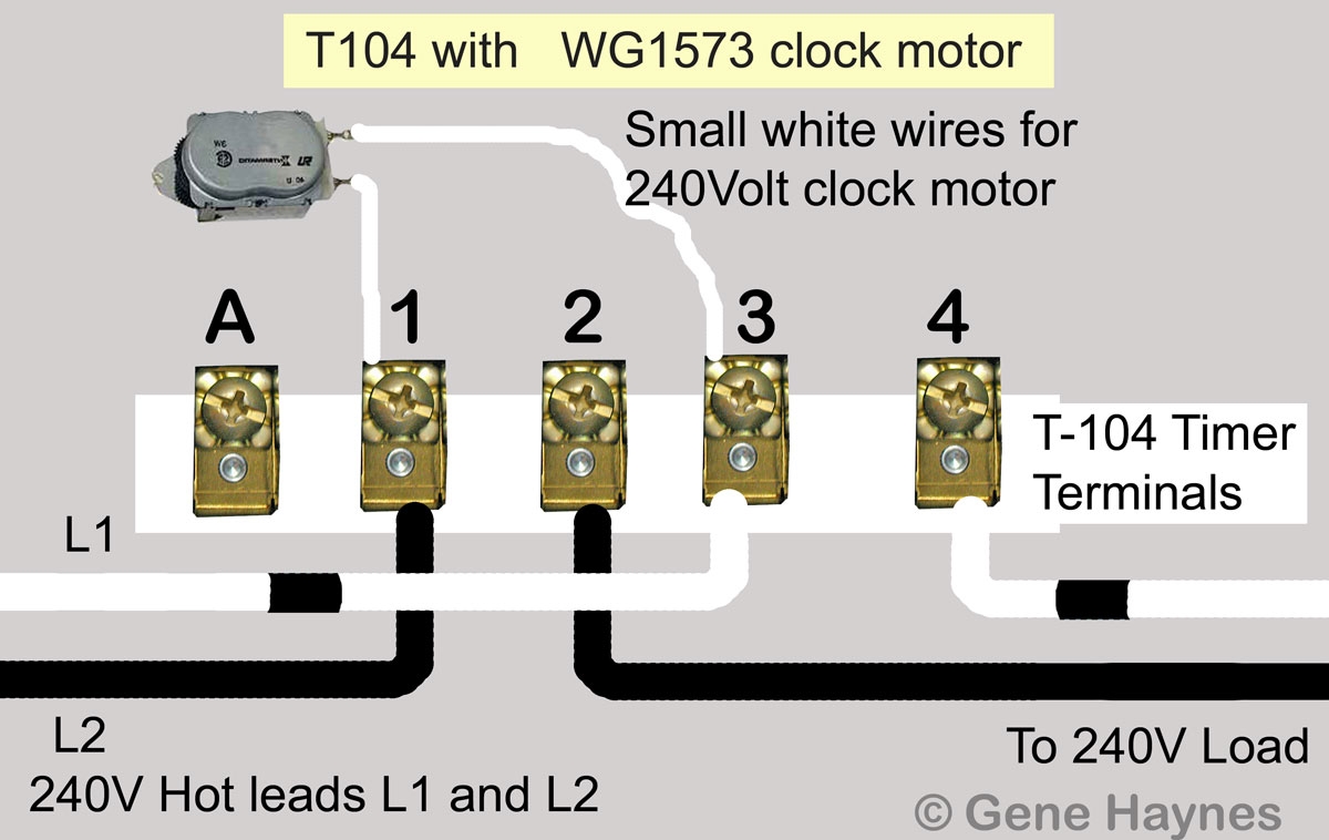
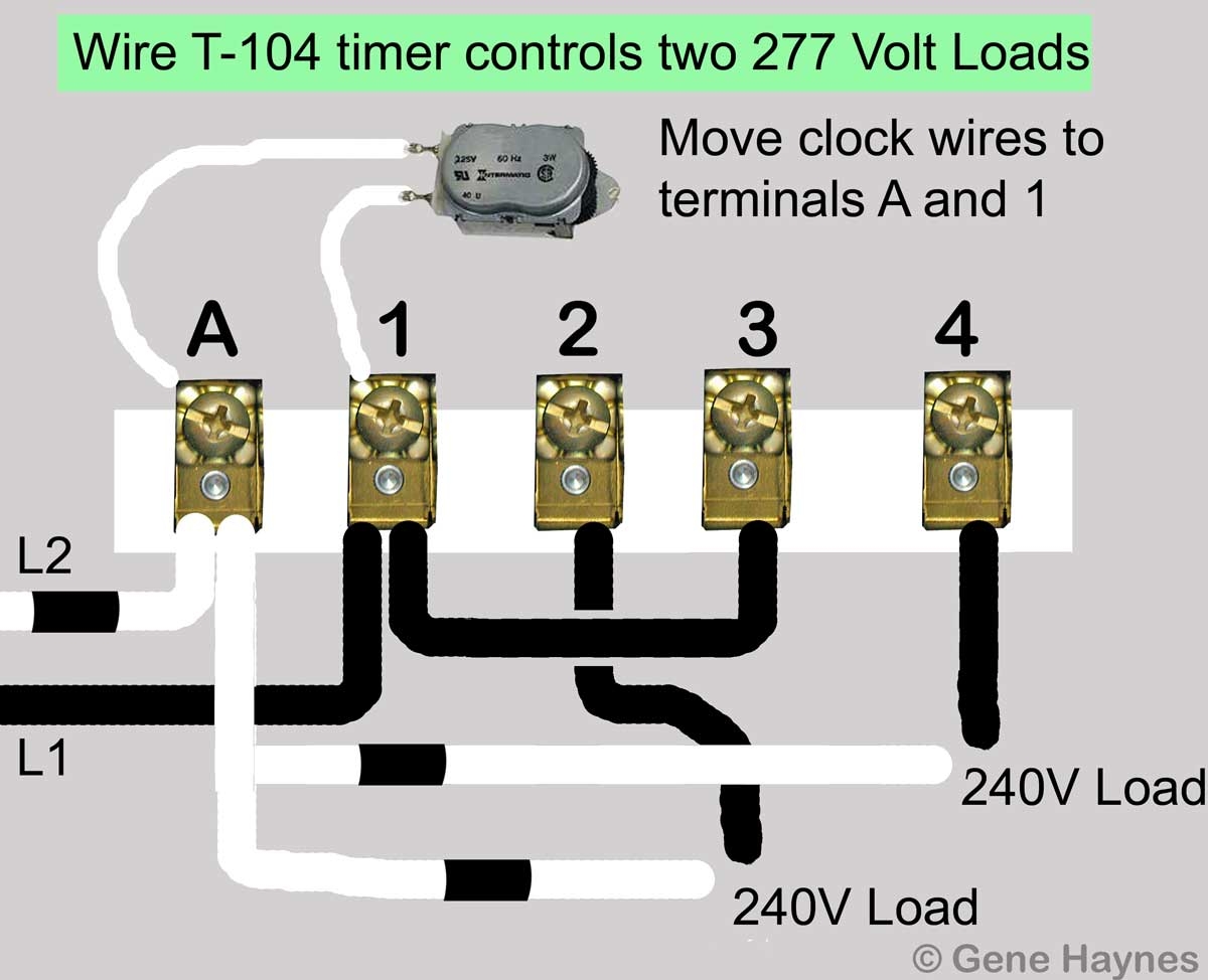
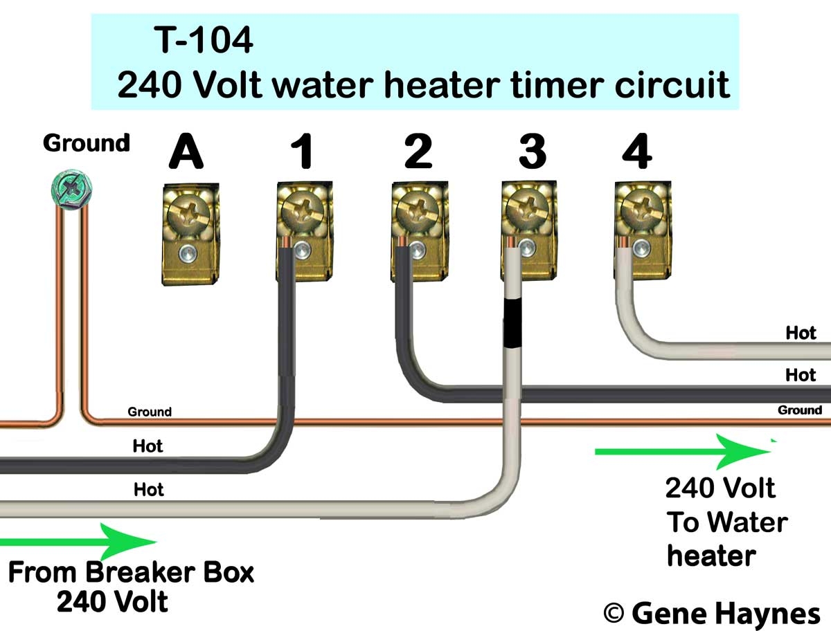
How To Wire Intermatic T104 And T103 And T101 Timers
The image title is How To Wire Intermatic T104 And T103 And T101 Timers, features dimensions of width 1200 px and height 758 px, with a file size of 1200 x 758 px. This image image/jpeg type visual are source from waterheatertimer.org.
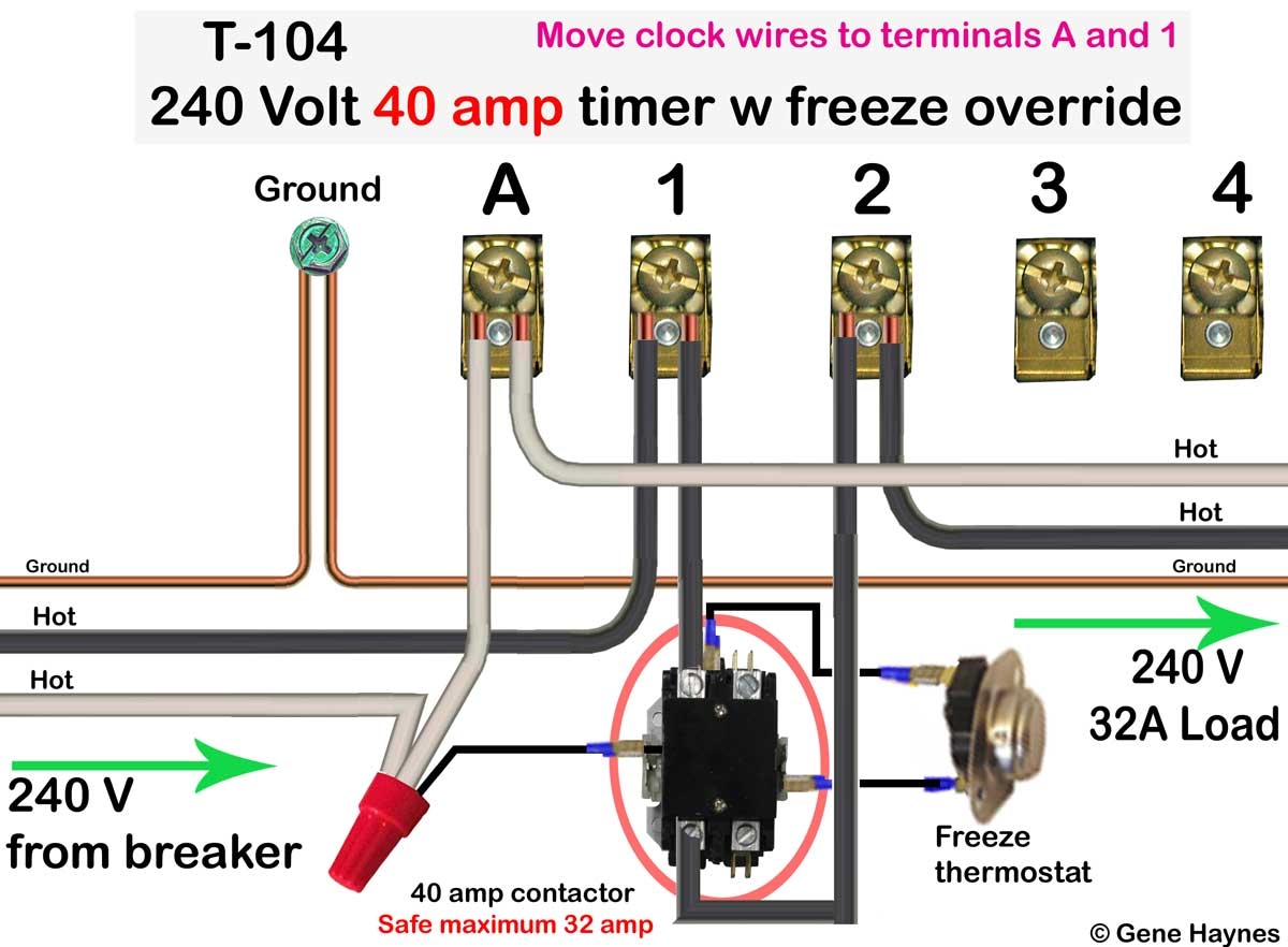
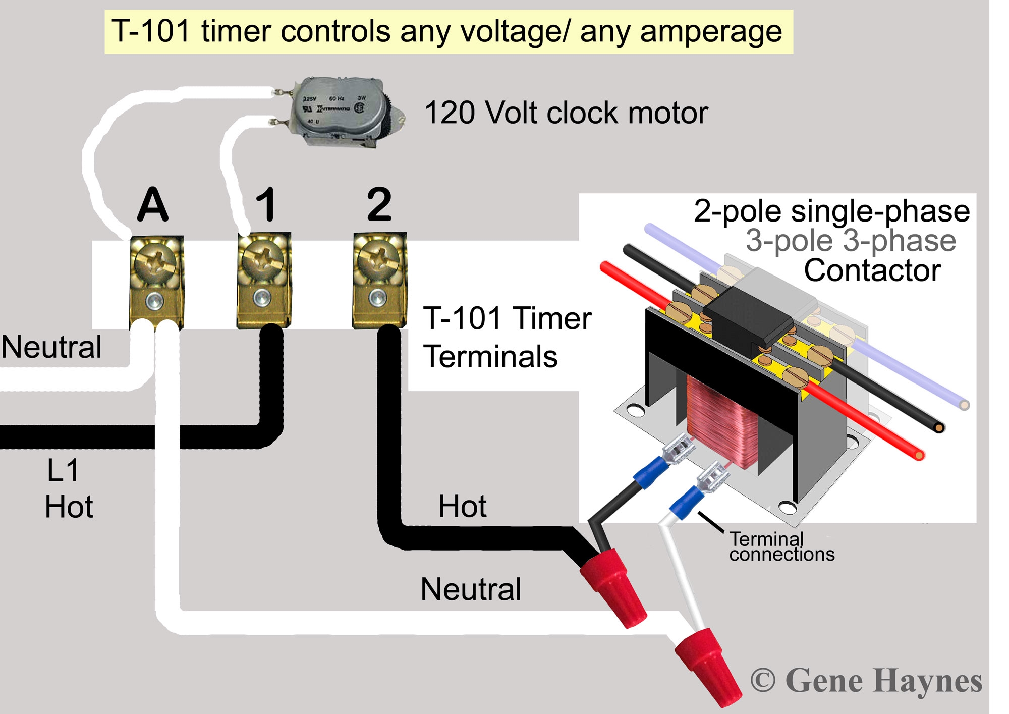
How To Wire T101 Timer
The image title is How To Wire T101 Timer, features dimensions of width 1200 px and height 882 px, with a file size of 1200 x 882 px. This image image/jpeg type visual are source from waterheatertimer.org.
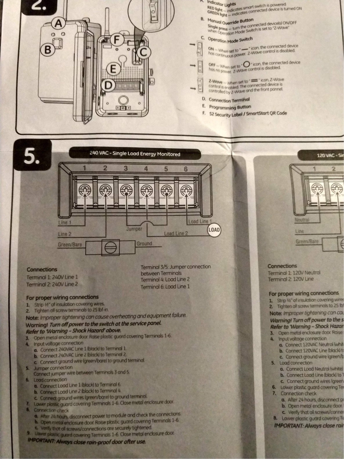
Electrical Identifying Wires In An Intermatic Pool Pump Timer Home Improvement Stack Exchange
The image title is Electrical Identifying Wires In An Intermatic Pool Pump Timer Home Improvement Stack Exchange, features dimensions of width 1186 px and height 1581 px, with a file size of 1186 x 1581. This image image/jpeg type visual are source from diy.stackexchange.com.
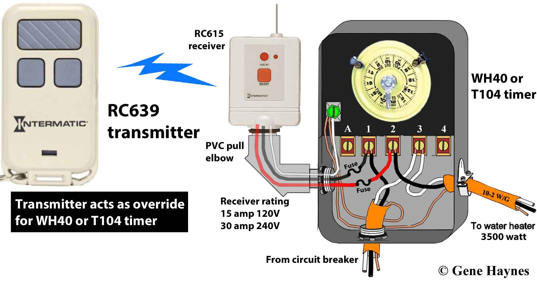
How To Wire Intermatic T104 And T103 And T101 Timers
The image title is How To Wire Intermatic T104 And T103 And T101 Timers, features dimensions of width 1876 px and height 986 px, with a file size of 1876 x 986. This image image/jpeg type visual are source from waterheatertimer.org.
How To Wire Intermatic T104 And T103 And T101 Timers
The image title is How To Wire Intermatic T104 And T103 And T101 Timers, features dimensions of width 1200 px and height 974 px, with a file size of 1200 x 974. This image image/jpeg type visual are source from waterheatertimer.org
How To Wire Intermatic T104 And T103 And T101 Timers
The image title is How To Wire Intermatic T104 And T103 And T101 Timers, features dimensions of width 1200 px and height 912 px, with a file size of 1200 x 912. This image image/jpeg type visual are source from waterheatertimer.org.
How To Wire T101 Timer
The image title is How To Wire T101 Timer, features dimensions of width 2000 px and height 1415 px, with a file size of 2000 x 1415. This image image/jpeg type visual are source from waterheatertimer.org.
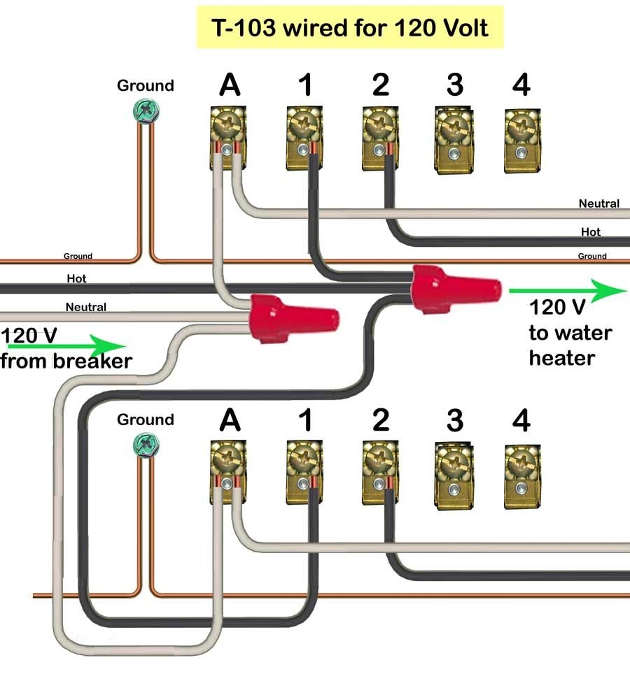
How To Wire Intermatic T104 Timer
The image title is How To Wire Intermatic T104 Timer, features dimensions of width 900 px and height 964 px, with a file size of 900 x 964.
The images on this page, sourced from Google for educational purposes, may be copyrighted. If you own an image and wish its removal or have copyright concerns, please contact us. We aim to promptly address these issues in compliance with our copyright policy and DMCA standards. Your cooperation is appreciated.
Related Keywords to 120v Intermatic Timer Wiring Diagram:
120v intermatic timer wiring diagram,how to set up intermatic light switch timer,how to wire a 220v intermatic timer,how to wire intermatic digital timer,light timer intermatic instructions
