Table of Contents
The Ultimate Guide to Understanding 02 Sensor Wiring Diagrams
Unlocking the Power of 02 Sensor Wiring Diagrams
When it comes to diagnosing and troubleshooting your vehicle’s oxygen sensor, having a clear understanding of the 02 sensor wiring diagram is crucial. This diagram serves as a roadmap that guides you through the intricate network of wires and connectors, helping you pinpoint issues with precision and accuracy. By unraveling the complexities of the 02 sensor wiring diagram, you gain valuable insights into your vehicle’s engine performance and emission levels, paving the way for efficient repairs and maintenance. Let’s delve into the world of 02 sensor wiring diagrams and discover how they can revolutionize your automotive endeavors.
The Basics of 02 Sensor Wiring Diagrams
Before we dive into the intricacies of 02 sensor wiring diagrams, it’s essential to grasp the fundamental principles behind these diagrams. At its core, an 02 sensor wiring diagram illustrates the electrical connections between the oxygen sensor, engine control module (ECM), and other relevant components in the vehicle’s emission system. By studying this diagram, you can identify the sensor’s signal wire, heater circuit, ground connections, and more, enabling you to troubleshoot issues effectively.
Key Components of an 02 Sensor Wiring Diagram
Signal Wire: Carries the voltage signal from the oxygen sensor to the ECM.
Heater Circuit: Powers the oxygen sensor’s heating element for optimal performance.
Ground Connections: Ensure proper grounding for the sensor to function correctly.
Reference Voltage: Provides a stable voltage source for sensor operation.
Interpreting 02 Sensor Wiring Diagrams
Navigating through an 02 sensor wiring diagram may seem daunting at first, but breaking it down into digestible chunks can simplify the process. Start by identifying the sensor’s location in the vehicle and tracing the wires back to the ECM. Pay close attention to the color codes, wire labels, and connector pins to establish a clear connection map. By following the signal path and analyzing voltage readings, you can troubleshoot sensor malfunctions, circuit faults, and wiring issues effectively.
Tips for Decoding 02 Sensor Wiring Diagrams
Use a multimeter to test voltage, resistance, and continuity along the sensor circuit.
Refer to the vehicle’s service manual for specific wiring diagrams and diagnostic procedures.
Document your findings and observations to track progress and facilitate future repairs.
Practical Applications of 02 Sensor Wiring Diagrams
Beyond mere troubleshooting, understanding 02 sensor wiring diagrams can enhance your overall vehicle maintenance practices. By proactively monitoring sensor signals, detecting abnormalities, and rectifying wiring issues, you can optimize engine performance, fuel efficiency, and emission control. Whether you’re a seasoned mechanic or a DIY enthusiast, mastering the art of interpreting 02 sensor wiring diagrams empowers you to take charge of your vehicle’s health and longevity.
Benefits of Proficient 02 Sensor Wiring Diagram Analysis
Improved diagnostic accuracy and efficiency
Enhanced vehicle performance and emissions compliance
Cost-effective repairs and maintenance solutions
Empowerment to tackle complex engine issues with confidence
In conclusion, delving into the intricacies of 02 sensor wiring diagrams opens up a world of possibilities for automotive enthusiasts and professionals alike. By honing your skills in interpreting these diagrams, you equip yourself with the tools needed to troubleshoot, diagnose, and repair oxygen sensor-related issues effectively. Embrace the power of 02 sensor wiring diagrams as your gateway to unlocking the full potential of your vehicle’s emission system and engine performance.
Related to 02 Sensor Wiring Diagram
- 02 Sensor Wiring Diagram
- 1 Light 2 Switch Wiring Diagram
- 1 Light 2 Switches Wiring Diagram
- 1 Ohm 4 Ohm Dual Voice Coil Wiring Diagram
- 1 Ohm Sub Wiring Diagram
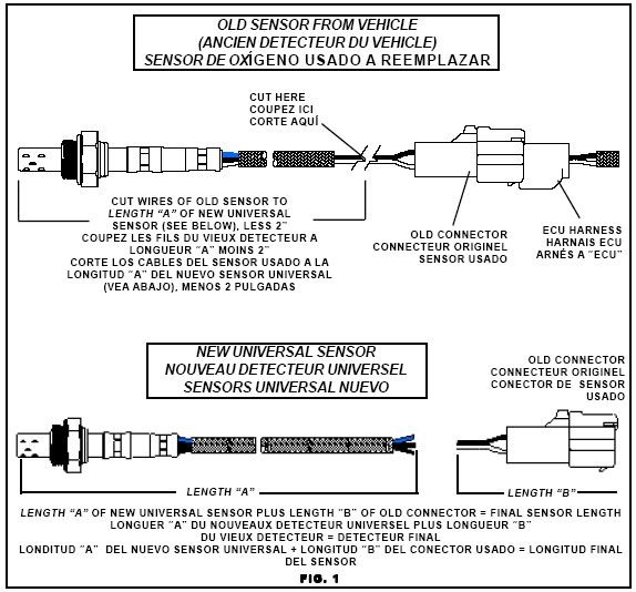
Sensor Schematics At DuckDuckGo Electronic Schematics Sensor Diagram
The image title is Sensor Schematics At DuckDuckGo Electronic Schematics Sensor Diagram, features dimensions of width 574 px and height 534 px, with a file size of 574 x 534 px. This image image/jpeg type visual are source from www.pinterest.com.
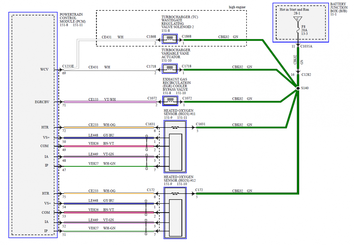
Oxygen Sensor Testing Wiring Diagram Confusion 2 0L EcoBoost Ford Edge Forum
The image title is Oxygen Sensor Testing Wiring Diagram Confusion 2 0L EcoBoost Ford Edge Forum, features dimensions of width 1200 px and height 830 px, with a file size of 1200 x 830 px. This image image/png type visual are source from www.fordedgeforum.com.
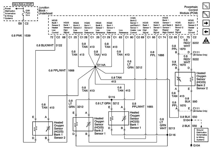
GM O2 Sensor Wiring Diagram Sensors 2001 02 6 0l With Isolated Ground Sensors Only Sensor Diagram Engineering
The image title is GM O2 Sensor Wiring Diagram Sensors 2001 02 6 0l With Isolated Ground Sensors Only Sensor Diagram Engineering, features dimensions of width 736 px and height 516 px, with a file size of 736 x 516. This image image/jpeg type visual are source from www.pinterest.com.
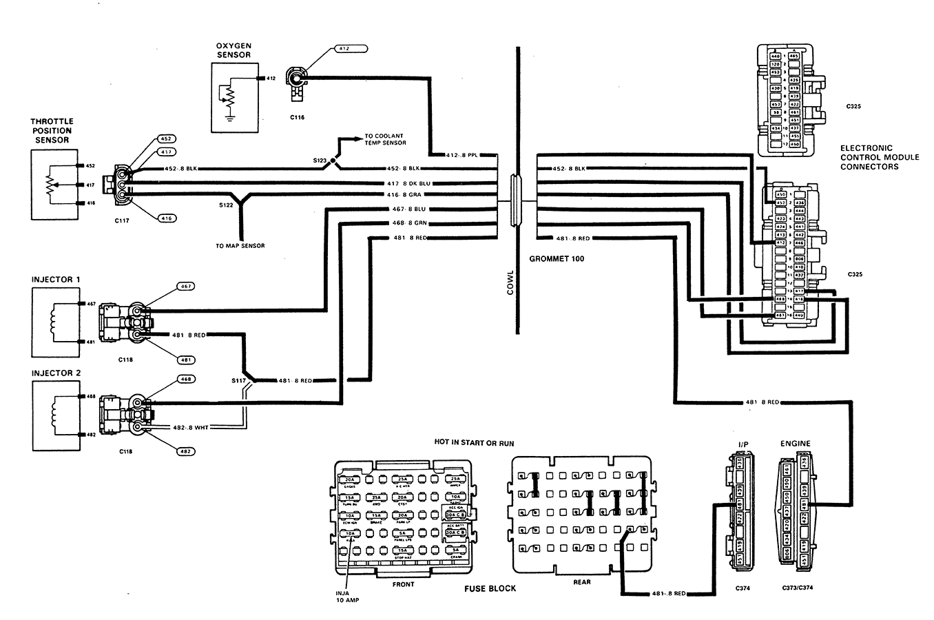
GM 4 Wire O2 Sensor Wiring Diagram Chevy 1989 Oxygen Sensor Wiring
The image title is GM 4 Wire O2 Sensor Wiring Diagram Chevy 1989 Oxygen Sensor Wiring, features dimensions of width 1356 px and height 900 px, with a file size of 1356 x 900. This image image/png type visual are source from www.justanswer.com.
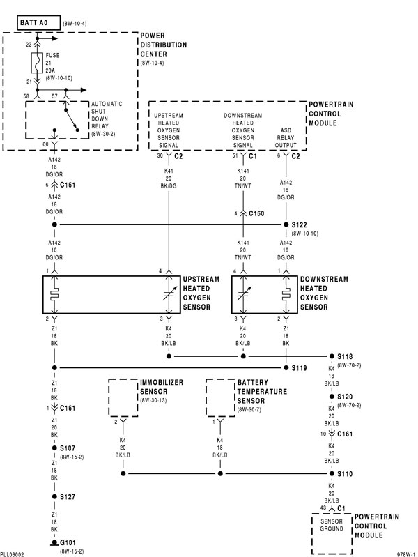
O2 Sensor Wiring Diagram Neons
The image title is O2 Sensor Wiring Diagram Neons, features dimensions of width 600 px and height 799 px, with a file size of 600 x 799. This image image/jpeg type visual are source from forums.neons.org
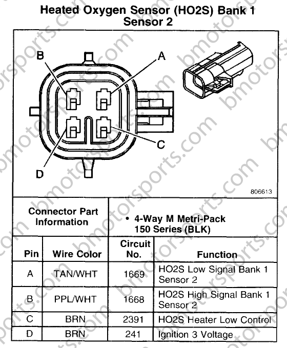
Chevrolet 2008 Chevy 2500HD 6 0L Motor Vehicle Maintenance Repair Stack Exchange
The image title is Chevrolet 2008 Chevy 2500HD 6 0L Motor Vehicle Maintenance Repair Stack Exchange, features dimensions of width 560 px and height 679 px, with a file size of 560 x 679. This image image/png type visual are source from mechanics.stackexchange.com.
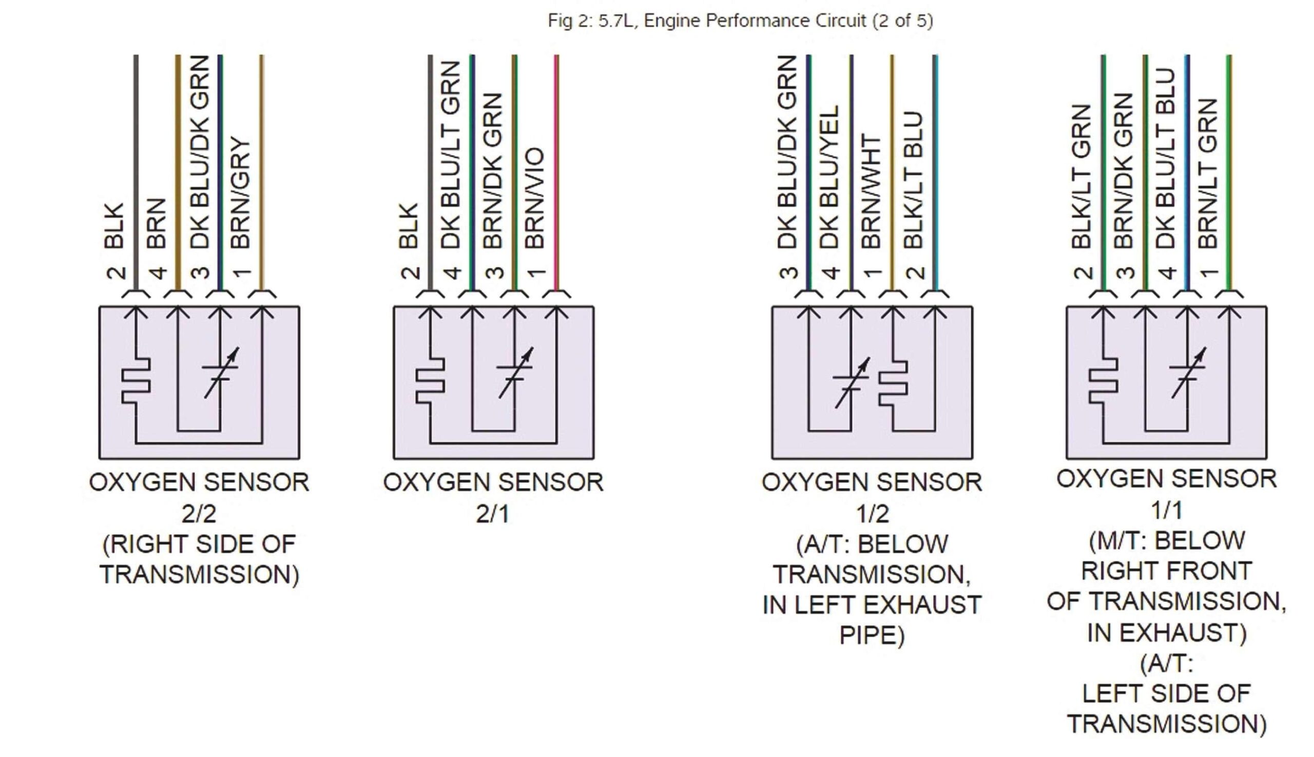
Tracing Sensor Wiring And Checking For Lazy Sensors Issuu
The image title is Tracing Sensor Wiring And Checking For Lazy Sensors Issuu, features dimensions of width 2560 px and height 1475 px, with a file size of 2702 x 1557. This image image/jpeg type visual are source from issuu.com.
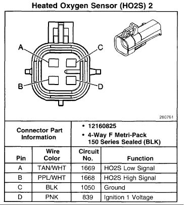
Toyota Oxygen Sensor Pinout Electrical Wiring Diagram Map Sensor Sensor
The image title is Toyota Oxygen Sensor Pinout Electrical Wiring Diagram Map Sensor Sensor, features dimensions of width 364 px and height 405 px, with a file size of 364 x 405.
The images on this page, sourced from Google for educational purposes, may be copyrighted. If you own an image and wish its removal or have copyright concerns, please contact us. We aim to promptly address these issues in compliance with our copyright policy and DMCA standards. Your cooperation is appreciated.
Related Keywords to 02 Sensor Wiring Diagram:
02 sensor wiring diagram,denso 02 sensor wiring diagram,oxygen sensor circuit diagram,oxygen sensor wiring diagram,oxygen sensor wiring diagram toyota
